Tag Archives: electrics

Maximum power

I’ve been having some difficulty with my battery slowly running down over time, in spite of installing a second solar panel. I’d been advised to install a maximum power point tracking (MPPT) charge controller.

Solar panels don’t produce consistent power at all voltages. If you connect them directly to your battery their voltage is pulled down to around 12V, but many produce more power at around 20V. In fact, the ideal voltage varies with the light conditions.

An MPPT controller has a voltage converter to allow the panels to stay at a higher voltage, and it has a processor that adjusts that voltage to track the maximum power point.

But beware, many Chinese suppliers are sticking the letters MPPT on everything to get sales. Some controllers have even changed from being MPPT to not because manufacturers have economized on components. This is all fraudulent, of course, but hard to police.

YouTubers to the rescue. Amateur enthusiasts on YouTube like to review gadgets, and these helpful videos by Adam Welch reviewed a low cost controller.

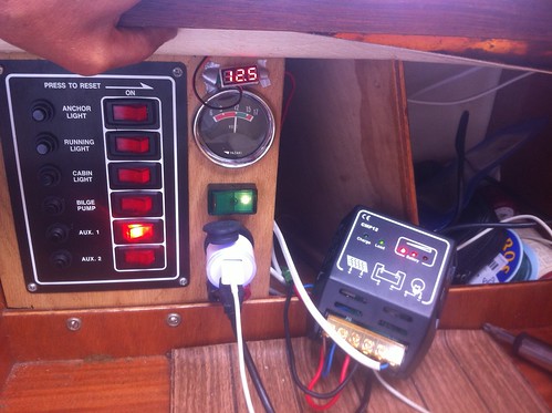
I now have one of these installed on Tammy Norie and it appears to be doing the job nicely. I’ve been able to connect my two panels in series rather than parallel so that they’re producing over 12V even in quite low light. The controller seems to hold the combined voltage at about 48V in sunlight, suggesting that my NASA panels have a maximum power point around 24V.

IMGA0607

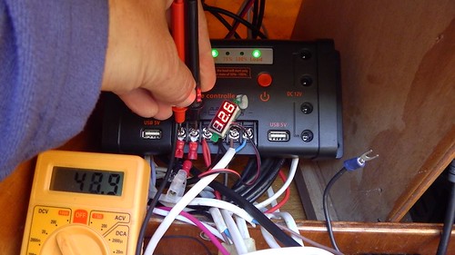
I haven’t been able to get an accurate current measurement. My meter seems to upset the controller, which may indicate that it’s doing something quite delicate. Time will tell if this scheme works well and I will report back.

In the meantime, this is the eBay listing I used. Worth a try for £25 I thought.

Update 2017-09-19: So far this is not working very well and I don’t suggest buying this until until I’ve had a chance to do more experiments.

Leave a comment

Filed under battery, electrics

Bow light LED hack

WARNING

Before you install LED bulbs in your fittings please consider carefully how they might affect the colour and visibility arcs of your lights and the insurance of your boat. Please check MGN 393 Navigation light units: maintenance and the use of new technology light sources, such as light emitting diodes (LEDs), as navigation lights on SOLAS and non-SOLAS vessels and also I suggest Warning not to use LED bulbs in filament bulb navigation lights from PBO.

My battery ran very low after my 32 hour passage from Rye to the Breskens. The main power draws were the tiller pilot, the VHF, and the navigation lights. The lights were the worst, drawing over 2A by the ammeter. I had incandescent bulbs that came with the boat: 10W in the stern and 25W in the bow, so they ought to be drawing 2.9A.

The chandlery in Willemstad had a cool white (6000K) replacement for the stern bulb, but nothing suitable for the bow. If you put a 6000K LED behind the usual green plastic filter then it shows up as blue. The only solution I’ve seen for this is to use an expensive bi-colour LED bulb.

But the chandlery also had warm white (2500K) domestic LEDs with brightness equivalent to 25W. They ought to give the correct colour, and they were much cheaper. The only problem was the fitting.

Time for a quick hack with the soldering iron!

IMGA0739

I soldered some copper flex into the feet of the LED bulb.

IMGA0740

The spring contacts to the bulb unscrew and come out, leaving holes for the flex.

IMGA0741

The unscrewed contacts have a convenient hole drilled down the centre. I threaded the flex through these holes.

IMGA0742

Then I just reassembled and tested the bow light.

IMGA0743

It showed the correct shades of green and red, as you’d expect, since the incandescent bulb would also be at about 2500K.

I taped the spring contacts to the old bulb and put it in the spares box along with the old stern bulb.  Nothing was destroyed by this hack and it’s easy to put things back as they were if necessary.

The current draw for the LED bow and stern lamps was about 200mA, less than a tenth of the incandescent bulbs.

4 Comments

Filed under lights, Repairs and Modifications

Wiring diagram

I’ve made this diagram (which is also on the “About” menu of this blog) in case anyone’s interested.

wiring diagram

wiring diagram

I’ll try to keep it up to date if anything changes. The only addition I’m expecting this year is a fixed VHF radio, probably a Standard Horizon GX2200 because it has built-in GPS and AIS, and so can provide me with a ship proximity alarm without any further equipment.

Here’s a slightly out-of-date picture of where the switch panel and most of the connections are located, under the bridge deck. The main difference now is that I have an integrated digital volt/ammeter that is much more responsive.

IMG_2888

17 Comments

Filed under battery, compass, Equipment, instruments

The solar panel

I’ve just written a reply to a thread asking about solar panels on the YBW forums, and I thought it’d be worth reproducing here for anyone interested.

I have a Nasa 20W through a CMP12 solar regulator to my Platinum SD685L 75Ah leisure battery, from which the main drain is the tiller pilot. I use the tiller pilot a lot as I’m usually solo, and the panel keeps up with the drain on a sunny day, and generally has no difficulty keeping up with the instruments and lights. My VHF is handheld and charged from the main battery occasionally.

I haven’t hooked up a sensitive ammeter and done the calculations yet. However, I do have one of these volt/ammeters with the ammeter in line with the battery and can highly recommend it. (I know then the solar panel is keeping up because the ammeter reads zero drain.) I filled the back of the meter with silicone electronic potting compound to keep the electronics from getting damp.

The solar panel was held down by duct tape on the aft locker for a lot of last year, but now it’s stuck down with a generous bead of Sikaflex. Nasa recommend this as a method. It suits me as it’s removable and doesn’t involve making holes in the boat, and especially not putting screws in the deck core, which you should never do.

Here’s a picture of the solar panel in its new position.  This spot is almost never in shadow.

IMGA0699

I just have to trim those Sikaflex blobs and clean off the old duct tape glue.

The wiring isn’t final either. I’ve looked at a few deck glands but there’s a fairly large connector on the other end of the wire, and I’d like to avoid cutting it off or making a hole in the boat. The wire actually squeezes nicely down the hinge side of the locker, so I might just fix it down (more Sikaflex) more or less where you see it, reinforce where it might chafe in the hinge, and then use some self-adhesive cable fixings inside to connect it forward.

6 Comments

Filed under battery, Equipment, Repairs and Modifications