Tag Archives: project

The Trials of my Hebridean

I have finally edited the video footage of my various trials of my Hebridean self steering system during and after my Netherlands cruise. This is a system I built over two weeks in July. Here’s the result.

Here are a few things I mention in the video that are worth repeating.

  • When I set off, my Hebridean was not complete and I had no experience with wind vanes.
  • This is a story about my Hebridean on my boat.
  • Very small boats and junk rigs may require mods to the plans.
  • I should have spent more time experimenting with the bungee.
  • Don’t copy me until you have tried the system according to the plans.

Thank you everyone for your help and support with this project. Special thanks to John Fleming for showing great patience when dealing with me. Paul Thompson for keen technical insight. And Stephen Crowther for useful observations and support.

I’m sure the story’s not over yet, but part one is complete.

9 Comments

2015-09-14 · 21:42

Replacing the pendulum on the Hebridean

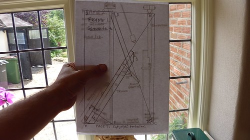
After spending a good 100 hours constructing my Hebridean wind vane I grew quite frustrated when it started to go wrong, especially after such initially promising results. However, after some very useful comments from readers I set about constructing a temporary replacement pendulum.

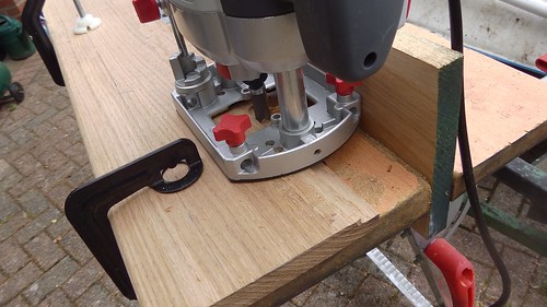
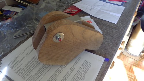
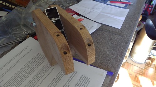
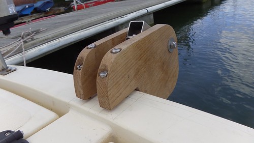
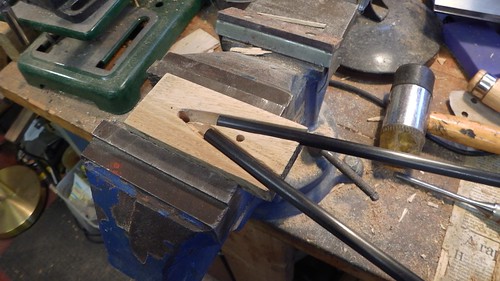
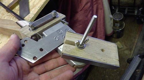
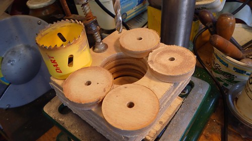
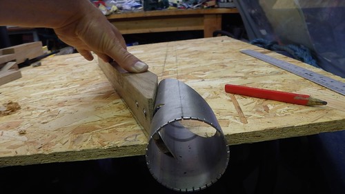
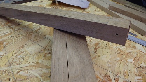
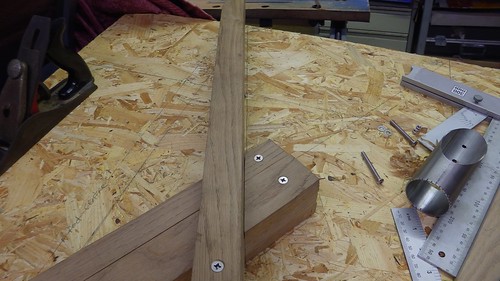
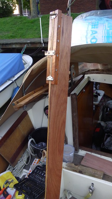
I started out with some 18mm plywood and a couple of hardwood blocks bought from the local Hubo.

IMGA0305

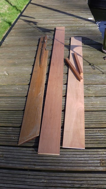
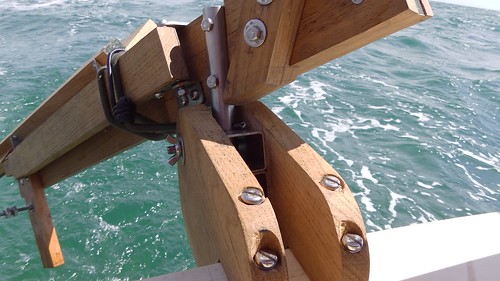
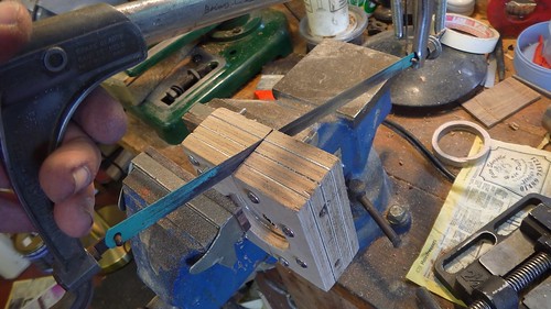
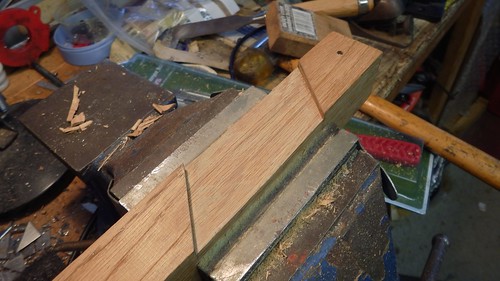
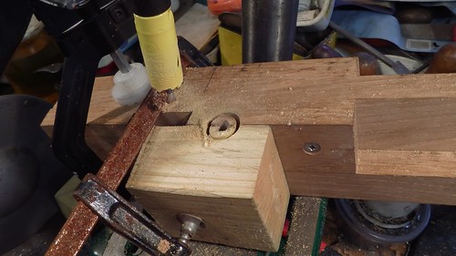
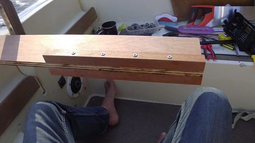
I didn’t glue the blocks to the plywood, instead using four big stainless steel screws through each, being careful to offset them slightly so they didn’t clash.

IMGA0306

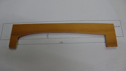
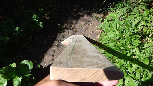
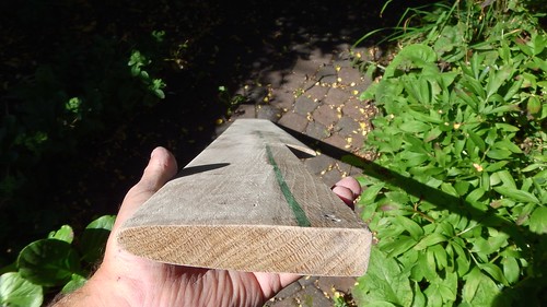
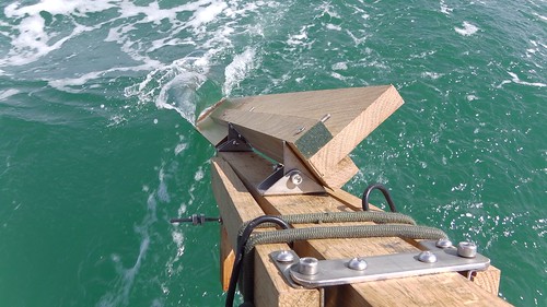
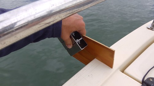
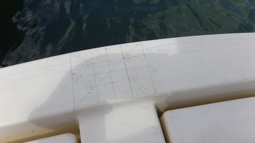
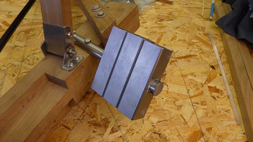
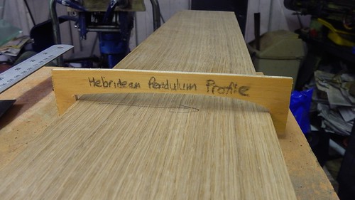
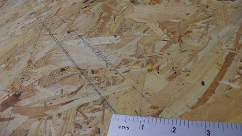
Then I marked off 9mm from each side of the leading and trailing edges, sharpened my plane, and set about adding a 45° bevel to the leading and trailing edges.  The plywood makes this easy to get right since it has a built-in gradient.

IMGA0308

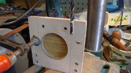
I noticed there was a slight curve in my plywood, but hoped that removing the pendulum balance cut-out would prevent this being an issue. I was expecting to have to add some balance later.

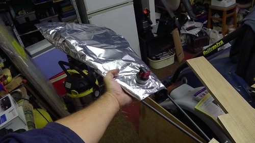
I put on a few coats of Cuprinol Ultimate to help keep the water out.

IMGA0310

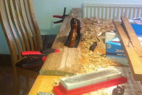
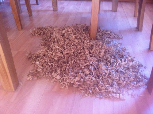
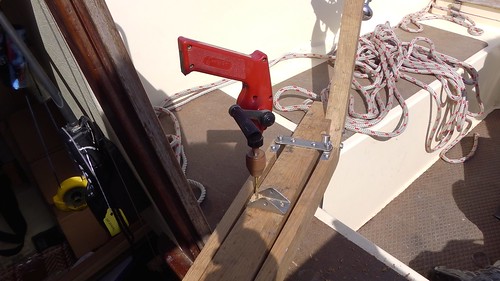
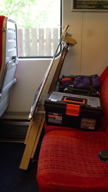
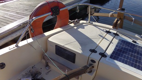
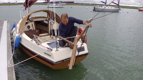
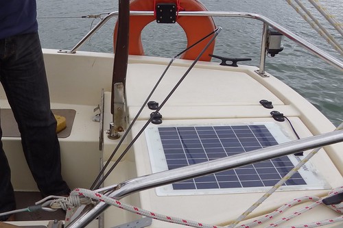
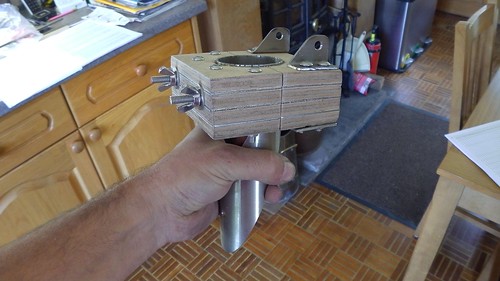
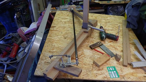
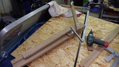
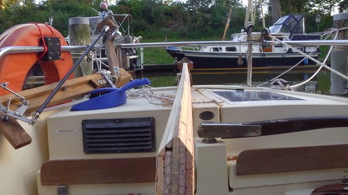
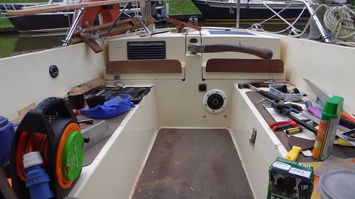
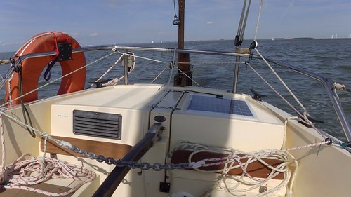
I was deliberately doing all the work in Tammy Norie’s cockpit, to see what it was like. Well, this is what the cockpit was like, anyway.

IMGA0322

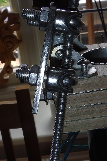
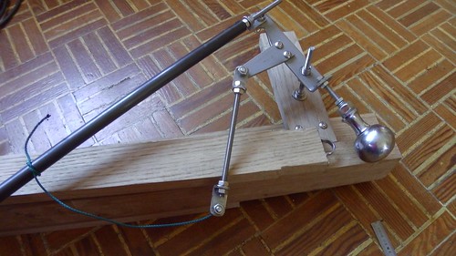
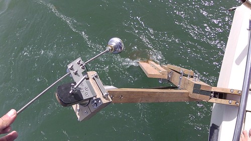
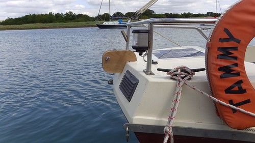
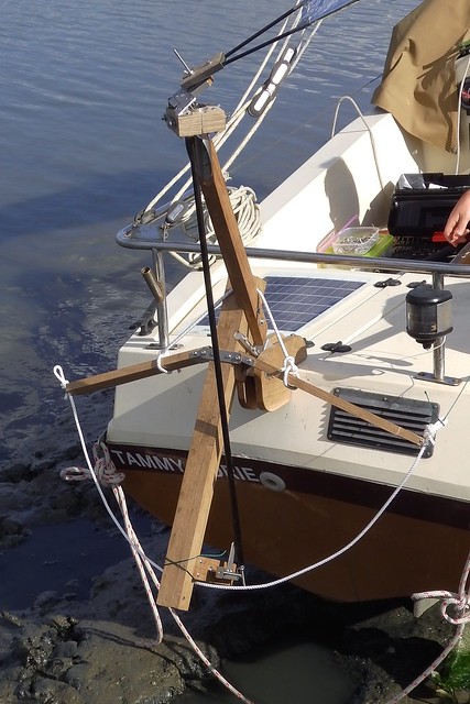
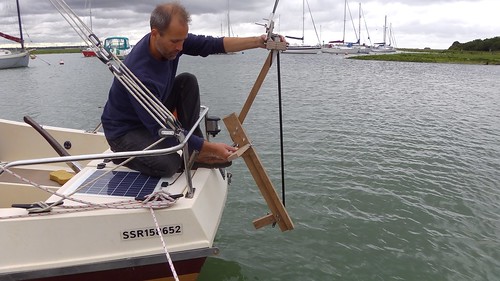
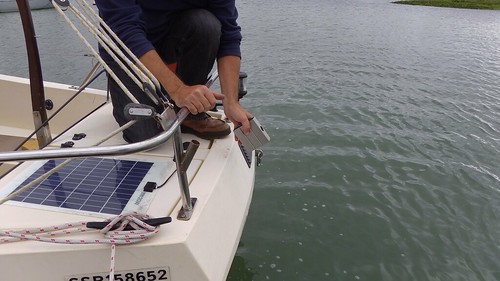
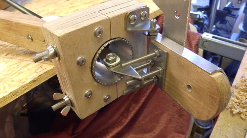
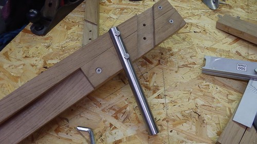
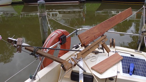
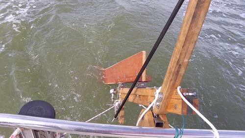
I attached the pintles and mounted the pendulum onto the Hebridean frame.

IMGA0325

Later that day I sailed from Harlingen to Den Oevre. Actually, I mostly motorsailed due to adverse wind and current, and the need to make the weather window in the North Sea. But I did spend about an hour trying out the Hebridean on various upwind courses in what was about a force 3 or 4.

IMGA0363

It seemed to work really well. With the linkage disconnected the pendulum was stable and would return to the centre position. With the linkage connected and the vane in place, but no tiller connection, the vane behaved itself very well. Attaching it to the tiller worked just fine and the boat steered nicely. There was no obvious lack of sensitivity, though truly light wind tests have yet to come.

IMGA0366

After picking up Martin Roberts at Den Oevre and motoring out past Den Helder we reached our departure point, and I set up the Hebridean for downwind.

IMGA0392

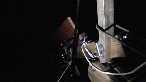
It worked well, and continued to work for the entire 36-hours that followed, taking us across the North Sea. For the second half of the trip it was set to a dead downwind course and took us through some pretty big and steep wave conditions.

The only problems were with the control line setup. I’d used some simple twine to attach various blocks and eyes on a trial basis, and these chafed through after 24 hours of continuous action. This put us off course temporarily on a couple of occasions but nothing serious went wrong.

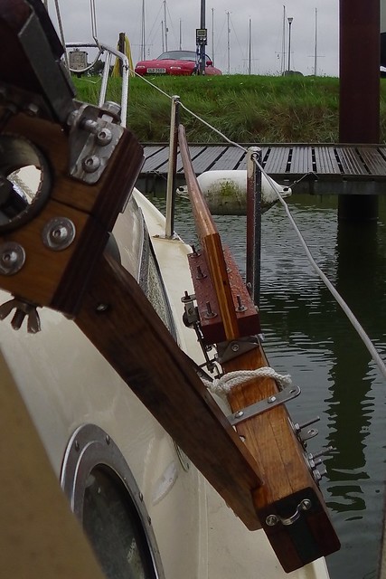
We didn’t disconnect the Hebridean until we had to cross the infamous bar on the river Deben, and I lifted it off completely when we put in to Tide Mill yacht haven. Looking at it then, it was clear that the plywood had curved further, but unlike the original pendulum this didn’t cause any noticeable problems.

IMGA0446

I spent a lot of time wondering about all this and discussing it with my crew.  We went over all the suggestions, John Fleming’s instructions, and John’s feedback during the journey.

Our theory is this: John mentions that he expect instability that is dampened when the Hebridean is connected to the tiller.  The thing is, the Coromandel has a small rudder and a very light tiller.  We suspect that it’s simply not providing the damping that John expects, so that the pendulum flips out.  Added to that, my pendulum seemed to develop a clockwise bias, and that made it always flip out in one direction almost immediately, overwhelming the vane.  The simple unbalanced pendulum doesn’t require damping to stay in line, so it behaves much better on my little boat.

It might also be insensitive and fail in light winds, but it seemed to be doing the job in F3.  I’ll know more when I try it out around the East Coast this month.

Anyway, I think we have discovered something important about the Hebridean and my boat, making the whole thing much more feasible for my Jester Challenge attempt.  I now believe it can be made to work. And I’ve also proved I can repair it in the cockpit!

2 Comments

Filed under Constructing the Hebridean, Netherlands Cruise 2015, Repairs and Modifications, self steering

Constructing the Hebridean day 13

I’m in the final stages of my project to construct a Hebridean wind vane self steering system. I brought the pendulum home to Cambridge so that I could work on shaping it into the computer-generated profile recommended by John Fleming in his plans.

You may recall that earlier I made a template from the plans out of a piece of thin plywood.

IMGA0317

I also experimented with using a router to get the basic shape of the profile, then planing to finish the job.

IMGA0341

IMGA0342

I would have continued with this technique, but I don’t have a router or any other suitable power tools in Cambridge.  I did look in to using a CNC router at Makespace to get a perfect profile, but in the end I just went to Mackays and bought a plane and sharpening stone (things I wanted anyway) and did the job by hand on my dining room table.

IMG_3330

I started by getting the bottom end of the pendulum into the correct shape.  This end is going to be cut off since the pendulum is way too long for Tammy Norie, so I could afford to get into practice.  I applied greatest pressure with the plane at this point and eased off towards the top, so that less wood was removed.  I then moved up the pendulum, using the template as a guide.  This gradually copied the shape from the bottom end up along the whole plank.

To fine tune the shape, I used a marker pen to mark where the template was touching the surface.  It was then easy to plane away the mark and take another look.  This gradually corrected the profile over the whole pendulum.

I did about three hours of planing last night and another two this morning, followed by about 30 minutes of sanding, with this result.

IMGA0484

IMGA0485

It’s very close.  There are some minor wobbles that I’ll correct, but I think the job is done.  So I’d say allow six hours for planing your pendulum.

I had to sharpen the plane about once per hour, and especially when it was new. This video on how to sharpen a plane was very helpful, and allowed me to get a very good cutting edge.

I’m also left with about a third-of-a-plank’s worth of oak shavings!

IMG_3331


6 Comments

Filed under Constructing the Hebridean, Equipment, Repairs and Modifications, self steering

Constructing the Hebridean day 12

This past weekend I sailed from Fareham to Emsworth and back with a friend from Cambridge, and while aboard (and under way!) I assembled and attached the incomplete pendulum and was able to test some aspects of the Hebridean wind vane self steering gear that I have been constructing since last Monday.

Before setting out, I finished making and attaching the counterweights. These balance the vane and push rods so that wind pressure is able to twist the pendulum. John Fleming’s plans involve creating counterweights by setting lead shot in polyester resin. But Dad has a better idea. He found a couple of old doorknobs and we filled them with lead instead.

IMGA0389

I tapped 10mm threads into the handles, then tapped 6mm threads into some 10mm threaded rod, so that the counterweights could be bolted to 6mm threaded rod on the Hebridean.  This also allows for some adjustment in their position with lock nuts.

I attached the upper counterweight to the vane and fiddled with it until the vane just returned to vertical.  It’s then that I found out exactly what the “grub screw” is for.  It tilts the upper counterweight arm so that you can get the vane vertical.

IMGA0386

The lower counterweight balances the push rod mechanism.  You need to detach the vane and pendulum, but hang the pendulum push rod so that you get the right weight.

IMGA0390

You then position the lower counterweight until the main push rod moves up and down with minimal force.

With these things done, I took the frame and pendulum aboard Tammy Norie. While underway I attached the pendulum sides and hinges.  Drilling oak with a little hand drill is slow going, especially when the helm is tacking every few minutes!

IMGA0418

The results were very satisfying. I was able to get the pendulum into the water while under way and see how it moved the whole gear when twisted.

IMGA0449

This kind of testing also revealed problems.  I left the end of the extension proud of the trunk, to keep that end of the cross-lap joint strong.  Unfortunately, it clashes with the mount and prevents the pendulum being fully lifted out of the water.  I’ll need to trim it down.

IMGA0450

There’s another issue with the pivot and mount.  I made the mount as a sandwich (as recommended) but this means that the split pins keeping the pivot in the mount clash with the sides, preventing the Hebridean from rotating.  I’m not sure what John intended here.  I notice that his boat has the mount in a different orientation so perhaps he didn’t notice this problem.

Later on I was able to attach the whole push rod linkage to the pendulum.  Once that was done it was possible to steer the Hebridean by wiggling the vane counterweight rod.

IMGA0476

I even have a video of this bit!

Unfortunately, this last test was taken just before we had to moor up, so I didn’t have time to test using actual wind. As it was we only just got unloaded before the tide dried out Tammy. We even had to push the rowing boat through the mud to get home.

I’ve taken the pendulum back home to Cambridge to shape it at home when I’m home from work.

3 Comments

Filed under Constructing the Hebridean, Equipment, Repairs and Modifications, self steering

Constructing the Hebridean days 9 to 11

I have taken a bit more time off work to try to complete the Hebridean wind vane self steering gear that I started last week. I’ve also had quite a few visitors to Tammy Norie, and have been doing other work on her, so days 9 to 11 aren’t days of solid workshop, as they have been up to now.  However, quite a few important things have been done.

Firstly, I’ve made the mount.  I started off by making a template while aboard, based on the position I found for the pivot pin using my foot a few days ago.

IMGA0361

Using this I shaped an offcut from the oak planks to make two sides for the mount, that clamp in the socket for the pivot pin.

IMGA0366

IMGA0367

The pendulum is held down in the water by friction between these blocks, so that if it hits an obstacle in the water it will swing up and save itself.

Having made the mount, I took it and the Hebridean (sans pendulum) to Tammy Norie yesterday. It’s amazing how many people stopped me to ask what it was! It’s quite an unusual contraption. One guy said “If you just told me it was a sculpture I would have believed you.”

IMGA0369

I marked up the transom for mounting bolts, took a deep breath, and drilled holes.

IMGA0371

Here’s the mount on the transom. You can see that it needs a bit more fitting to make it snug, but this is good enough for a bit of testing.

IMGA0374

IMGA0375

With that, I was able to attach the Hebridean. Quite a moment.

IMGA0376

Of course it’s not rigged up, and so I spend some time that day checking the various angles and lengths.  I have not yet cut down the outriggers to get the rudder turn angle correct with respect to the Hebridean’s tilt.  I just attached lines to the end of the current outriggers to get an idea.

IMGA0382

You can see that I’ve tilted the outriggers down slightly.  This is to avoid a potential clash with the anchor light.  It will reduce their effective length, but I don’t think it will affect operation.  Tammy Norie’s pushpit is very low and so the extra clearance will help.

Then I rigged up some string and blocks to test connection to the tiller.

IMGA0385

I realise I haven’t crossed over the lines yet.  I was just checking the rudder turn angle, so which way it turned was irrelevant.  I decided to re-use the tiller pilot’s pin as the tiller attachment.  I should be able to find a clip or chain that will sit nicely on it.  I really need to take a protractor to the boat to get a clear idea, but from my measurements the rudder is probably turning about twice as far as it should, and so my outriggers need to be considerably shorter!  I will test this under way with a jury rig before I make any cuts.

I’m now back at the workshop to work on the pendulum, counterweights, and a few other details.

A couple of days ago I was planing the pendulum to get the curved profile and realised it was going to take me a very long time.  So I did an experiment with a router.  By setting it up with a fence and carefully controlling the depth I was able to make a good approximation to the profile curve.

IMGA0341

A small amount of planing and sanding then made for a perfect fit.

IMGA0342

So I think I’ll extend this technique along the whole length (and the other side) to save a huge amount of work.  That’s what I’ll mainly be doing today.

1 Comment

Filed under Constructing the Hebridean, Equipment, Repairs and Modifications, self steering

Constructing the Hebridean day 8

The title of this post is a bit inaccurate, since I did no construction today at all. But I did bring the Hebridean frame, vane, and mount bearing to Tammy Norie and worked out how they will fit.

The first job was simply to locate a good position for the Hebridean on the stern.  This was quite easy.  As you can see from this picture, the Hebridean looks made for the boat, with its trunk angle nicely matching the top angle of the transom.

IMGA0328

There’s plenty of clearance all around, but the end of the pivot pin (resting on my toes) is just outside the boat. The mount bearing will sit here.

IMGA0333

It will be sandwiched between two planks which will be fastened to the boat. After a bit of thought, it’s clear that I should cut planks that are bolted down to the top of the transom, on the 80mm-wide flat part of the deck, but then are shaped to rest on the top slope of the transom to bear load.  This will keep the mount clear of the stern lockers and anything else going on in the cockpit.  I’ll make a proper diagram later and share it.

I also checked how the Hebridean will act when it swings.  I have yet to determine the correct length for the outriggers, and it’s not clear how I can do that before mounting and rigging the whole thing. There will be pulleys suspended from the stern rail taking lines from the outriggers to the tiller.  At the angle shown in the photo below the outrigger is exceeding the height of the rail, and that means the gear will stop working.  I wonder if it will have enough movement.

IMGA0329

One possible refinement is that the Coromandel’s tiller could be adapted to be reversible.

IMGA0332

Here you can see the tiller when vertical.  By making the bottom bolt removable (using an anchor pin, for example) the reinforcing the top link, the tiller will swing back over the stern lockers.  This would allow the Hebridean to connect without the usual cross-over of its lines, and also mean that the cockpit is clear then using the self-steering.

Anyway, I now have enough measurements to determine the correct length for the pendulum.

The rest of the day was taken up with a wonderful sail from Warsash to Fareham with my friend Gareth and his nephew and niece, Kyle (12) and Cara (10), neither of whom had been sailing before.  I’ll let the Met Office tell you about the weather:

Selsey Bill to Lyme Regis – Strong winds are forecast

24 hour forecast: West or southwest 6 to gale 8, occasionally 5 later. Moderate or rough. Mainly fair. Good.

We came out of the Hamble and messed around in Southampton Water for a while. The winds were strong, but it was also sunny and warm. The others weren’t due back until the late afternoon so we decided to take Tammy home to Fareham. It was a delightful run before a force 7 in 1m seas, and once again we had the Solent to ourselves.

IMG_2150

I also got to measure the distance from Tammy’s stern deck to the stern wave (about 310mm) while doing 6 knots in front of a force 7. That’s probably a good working figure for the Hebridean.

I will be sailing again tomorrow, and then I will need to return to work for a few days, so construction may be suspended for a short while.

1 Comment

Filed under Constructing the Hebridean, Equipment, Logs, Repairs and Modifications, self steering

Constructing the Hebridean day 7

I only did ten hours today on my project to build the Hebridean wind vane self steering gear.  For most of the previous six days I’ve been working 12-14 hours each day.  It’s Sunday and I felt like a bit of a lie in.

As on previous days, there are more photos in the Flickr album than I’ve shown here, with details in the descriptions.

I started today by making the vane itself.  This is the “sail” that gets pushed by the wind, twists the pendulum, rotates the trunk, pulls the tiller, and thus steers the boat.  It’s a framework of three carbon fibre tubes, filled with some kind of cloth, that attaches to the vane attachment I made yesterday.

The tubes are clamped in to something I’m calling the “vane end”.  John Fleming’s method for making this seems a bit complicated, involving blind drilling at strange angles and then starting again if you get it wrong.  I decided to cut grooves to hold the tubes instead, using a chisel and a round file.

IMGA0306

I had a short debate with friends on Facebook about why woodworkers avoid files, but I decided that a rasp is just a file in disguise and used one anyway.

One mystery is why the vane end isn’t arched like the vane attachment.  When you fix the vane at an angle it’s going to clash with the counterweight flange, like this.

IMGA0308

I’ve asked John about this, but he’s very sensibly not answering email on a Sunday.

Rather than start the pendulum as planned, I decided to work on the mount. This is the bearing that will attach the whole gear to the back of the boat. I started by making the bearing, which is three boxes bolted together with a large hole down the middle to take the pivot pin.

IMGA0312

Making the large hole took a long time and a lot of tallow.

IMGA0313

But I was pleased when it fit perfectly first time!

IMGA0314

That’s as far as I got with the mount today.  Before going further I plan to take the frame to the boat and make detailed plans about how I’m going to attach the bearing.

This evening I started on the pendulum. This is a kind of reverse rudder that twists, steering the gear and thus pulling on the tiller.  It’s basically a plank that you must plane into a wing-like profile.  The plans come with a computer-generated profile to copy. To do this, I copied the profile to a piece of thin plywood.

IMGA0317

This was done by first photocopying the page, cutting a groove through the copy with a knife, using a jigsaw to get it roughly right, then filing and sanding until I matched the line of the original.  This template will be used when planing the pendulum to get the shape right all the way along.

IMGA0319

I’ve started the planing just to get a feel for it, but haven’t got very far yet.

One other thing, at dinner we happened to come to the end of a wine box. Dad took out the bag to get the last of the wine. It’s a very nice strong mylar bag, and it’s just the right size to fill in the vane!

IMGA0320

So that’s that problem solved.

Tomorrow I’m sailing (with children!) in the morning, but hope to get some more construction done later in the day.

4 Comments

Filed under Constructing the Hebridean, Equipment, Repairs and Modifications, self steering

Constructing the Hebridean day 6

We’re into the sixth day of construction of the Hebridean wind vane self steering gear, since I started on Monday.  It’s getting close to complete assembly, with only the pendulum, vane, and mount to make.

This morning was taken up with building the vane base. This is a large block that clamps to the turret tube. You turn it in order to change course, because it controls the angle of the vane that is pushed by the wind.  In spite of being more or less a cube, it’s quite complicated, being made of four plys of wood and three of metal. John Fleming tells me this is to ensure that it copes well with wear.

As before, there are quite a few photos in the Flickr album with descriptions containing tips.

Once again, I deviated from John’s instructions. Having a drill press, I’m able to make accurate holes through quite long distances. That means I was able to cut and drill all the holes in all the layers of wood and metal in one go.

IMGA0274

It also meant I could make these long holes without needing to saw and chisel as instructed.

IMGA0282

One thing that does puzzle me is that John’s instructions for cutting the base in half involved separating all the pieces and cutting them individually.  I just cut the whole thing with a hacksaw in a couple of minutes.

IMGA0283

Here’s what the vane base looked like assembled.  Twisting the block around the turret tube is what will change the course of the boat.

IMGA0284

I also made the vane attachment.  This is a bracket which will hold the wind vane itself (the “sail” that gets pushed by the wind to keep a course).  Its main feature is a flange that will hold a counterweight, so that the vane is balanced.  It hinges on the vane base.  Here’s what it looks like when assembled with the vane on the frame.

IMGA0296

And here’s the frame almost completely assembled, with the vane attachment, vane base, and push rod linkages all put together at the end of the day.

IMGA0299

Once again, I have quite a few smaller tips in Flickr album that might help someone else building, or interest the very curious!

I’m writing this entry at the beginning of day 7, so now it’s time to get to work on the pendulum and vane.

2 Comments

Filed under Constructing the Hebridean, Equipment, Repairs and Modifications, self steering

Constructing the Hebridean day 5

It’s day five of my project to construct a Hebridean wind-vane self steering gear, and things are literally coming together.

I was somewhat stuck at the end of yesterday, not knowing how I should align the extension — the piece of the frame that has the vane at the top. I had quite a bit of back and forth with John Fleming, but he gave me a key bit of information: the carbon fibre push rod that comes down from the vane to the pivot is 30mm left of the line DE on the frame diagram.  Since it passes through the centre of the turret tube, I was able to use it to line everything up.

IMGA0238

IMGA0240

This allowed me to mark up and cut the cross lap join that’s so critical.  I wasn’t all that confident about this bit of woodworking.  The last time I made a cross lap joint was during ‘O’-level Design Technology at school. But it turns out to be much easier than I remember, as long as you sharpen your chisel until it’s like a razor. (The chisels at school were always blunt.)

IMGA0241

IMGA0246

IMGA0249

I made another deviation from John’s plans.  Since you need a 20mm hole saw to make the bearing for the pivot pin, why not use it to cut the groove for the same pin?  This saves a lot of delicate chisel-work.  It helps if you have a drill press.  Here’s the work in progress.  (More details in the Flickr album.)

IMGA0262

IMGA0266

Finally, I assembled the outrigger hinges. This was straightforward, and it’s great to see the fiddly stainless-steel parts I’ve been making start to make sense in context. Here’s what I have at the end of today.

IMGA0267

There are more photos with details of the steps in the Flickr album, including multiple checking steps.

But now it’s time for strawberries and bed.

1 Comment

Filed under Constructing the Hebridean, Equipment, Repairs and Modifications, self steering

Constructing the Hebridean day 4

I started construction of a Hebridean on Monday. I didn’t get very much construction done on Thursday for two reasons. Firstly, I went to a meeting of the Small Sailboat Club at Ashlett Creek and met (amongst others) Jim Hall on his amazing Paradox micro-cruiser, Faith. More about that later!

IMGA0215

The second reason was that I got stuck.  John Fleming’s plans for the Hebridean are sometimes quite tricky to follow.  At this stage, I should be joining the “extension” (upper arm that goes to the vane) to the “trunk” (main frame strut).  The instructions go in to great detail about the joint, but don’t tell you where to put it.  There is a serious lack of dimensions in the diagrams.  I even resorted to tracing to try to figure it out.

IMGA0193

I wrote to John and he seemed a bit baffled by my bafflement!  But he did include a very important dimension in his reply.  The vertical push rod’s centreline is 30mm left of D on the frame 1 diagram.  Since it passes through the centre of the turret tube, this locates the extension (and the pivot later on too).

It’s now Friday morning and I can start to join the frame together.  If it stops raining this afternoon I’ll take the frame to Tammy Norie and I can start designing the mounting on the back of the boat.  That part has to be custom for each boat, and I think Tammy’s will sit on top of the transom. We’ll see!

Leave a comment

Filed under Constructing the Hebridean, Equipment, Repairs and Modifications, self steering