Category Archives: Repairs and Modifications

Knackering lacquering

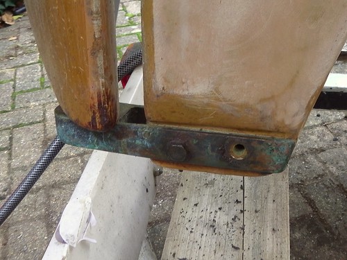
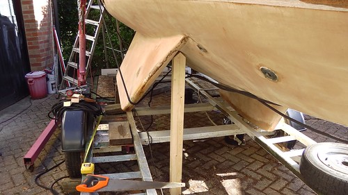
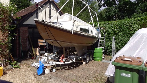
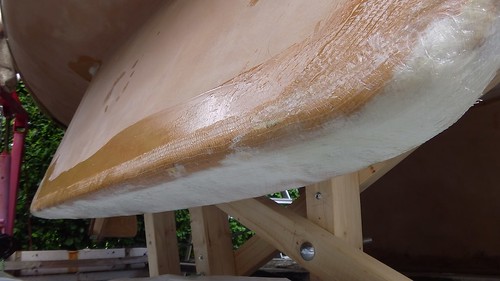
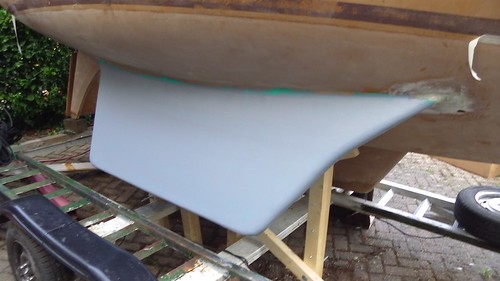
In my previous article I described how I removed, inspected, repaired, and faired the surface of Tammy Norie’s rudder. I was very pleased that this solved the riddle of Tammy’s “goosebumps” and eliminated osmosis as a cause. But I still plan to add an osmosis-preventing barrier coat to Tammy’s bottom, and the rudder is my second test area.

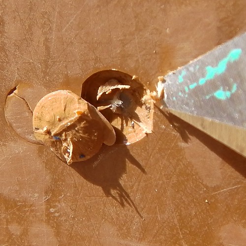
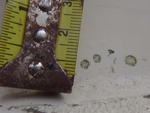
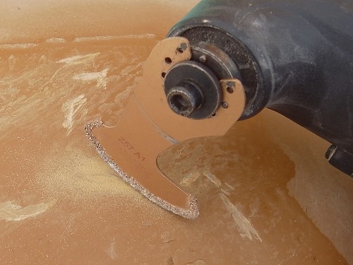
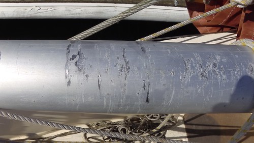
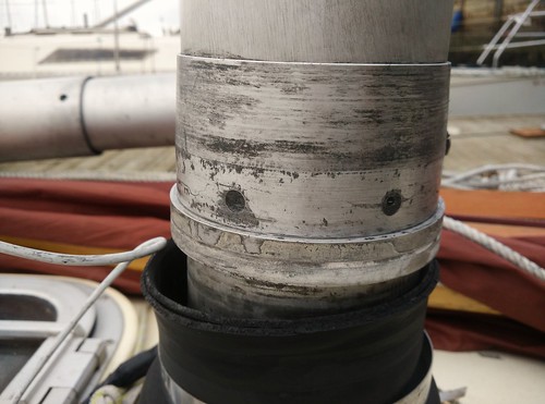
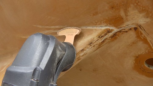
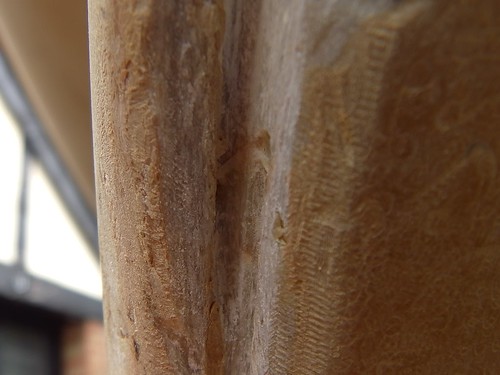
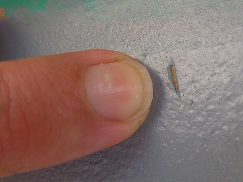
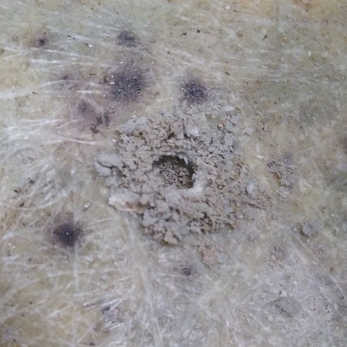
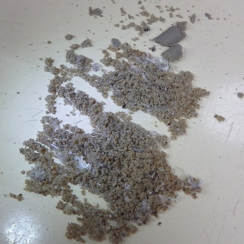
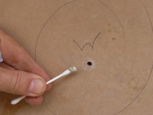
My first test area was the two keels. I had been planning to use International Gelshield as a barrier coat, and tried this out when I reinforced the keels earlier this year. I have to say I have not been impressed. It does seem easy to apply, but it also seems rather easy to remove! It’s very soft. Here’s a patch where I tried to fill a flaw on the keel, then (very lightly) sand it down to match. You can see through all the grey/green alternating layers back to the brown gelcoat.

IMGA0275

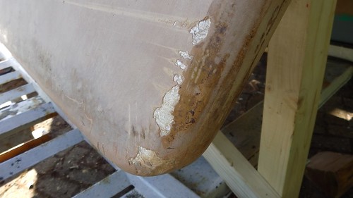
I’ve also had problems where the ropes used to lift the boat on the crane had easily worn through the Gelshield. It just doesn’t seem like a very strong surface. It would certainly come off the next time I scraped away the antifouling.

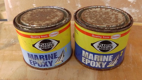
So I have decided to try out an epoxy barrier coat instead, using West System’s instructions. An epoxy resin layer will be much tougher than this paint-like Gelshield. On the Facebook group “Sailing on a Shoestring”, I came across a couple complaining about all the trouble they were having removing an epoxy barrier coat, until they realised that they didn’t need to. That sounds more like it. It also helps that Mads Dahlke has made a detailed video about applying it to his yacht, Athena.

The main difficulty is that applying layers of epoxy is technically more tricky than applying Gelshield, which goes on like paint. Epoxy resin cures into plastic by a chemical reaction that is mostly influenced by temperature, unlike paint, which dries in the air. While the epoxy is soft you can’t add another coat, because the weight will just drag it down. But once it’s hard you can’t add another coat, because the new coat won’t form chemical bonds with the one underneath. In between these two times the resin is firm, but the surface is tacky. There’s a supposedly short period of time to work with. What’s more, a barrier requires six coats.

(In fact, you can add new epoxy over completely cured epoxy, but you have to wait until it’s hard enough to sand, then sand it all to create a mechanical bond. Since it took me six months to sand Tammy’s bottom, I’m not keen!)

The good news is that West System provide all of their excellent manuals online, including a detailed manual about osmosis repair and prevention. This includes a very handy figure for selecting the epoxy resin hardener chemical.

West System’s epoxy hardener selection guide

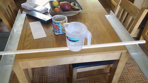
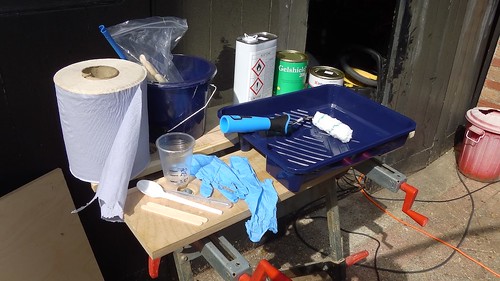
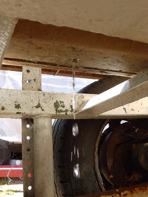
Since I’m often slowed down a lot by ME/CFS, I wanted to make sure I had plenty of time for coating. So I bought their 105 resin with their 206 slow hardener. Here it is set up in the kitchen over the radiator, so that it stays warm and runny.

IMGA0276

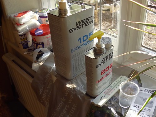
West System do not recommend the use of 206 below 16ºC because it’ll cure very slowly. But that’s just what I wanted. I had an idea that if I was unable to get the job done in one day, as recommended, then it might stay tacky over a cold night.

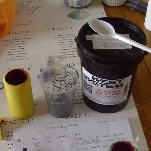
I also managed to lay hands on pots of their 422 barrier coat additive. My usual suppliers, East Coast Fibreglass Supplies, didn’t have any and couldn’t say when they’d have more. Fortunately, the lovely folks at YouBoat in Gosport had two 500g pots. Even better, they were three years out-of-date, and I got them half price!

Now I happened to know from my reading on osmosis that barrier coat additive is usually made of finely ground minerals, so a few years sealed in a pot are unlikely to affect it. A quick look at the safety data sheet for 422 confirmed that it was made of aluminium powder and mica. Bargain!

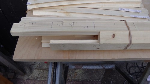
I did a few calculations to work out the quantity of resin I’d need. I’ll summarise these for others.

West System say to use 8-10 mini-pumps and add 56g of additive, confusing volumes with masses. However, the specific gravity of the resin is 1.18, so I was able to make this conform as 20%-25% by mass. In practice, this was about one heaped teaspoon per pump, according to the kitchen scales.

IMGA0292 - Version 2

West System say that one “B” pack of 4.55L mixed resin will cover 43-48m² of a non-porus surface. I calculate this as 8.5m²/kg. However, Mads Dahlke (in the video linked above) says that 10 pumps will cover roughly 2m², which is 7.1m²/kg. I’m not sure how he worked that out.

One side of the rudder is 0.2m², so that’s about 0.4m² overall, which works out as two pumps using Mads’ estimate. Convenient for mixing, but I did have some excess, so I think Mads is a bit conservative.

I’m not going to go over all the basics of how I applied the resin. For that, you can read the manual, watch Mads’ video (linked above), or even this brief one from West System.

What I will tell you is what I learned.

Firstly, don’t be put off. It’s pretty easy. I do recommend going through the process on a trial area, even a piece of scrap, so that you can get the hang of it and gain confidence.

Epoxy is not paint. It does not dry; it cures. When you roll out paint it starts to dry immediately, so you tend to proceed, say, from top to bottom. But with epoxy it’s a bit more like you’re rolling out dough over the surface. The best method I found was to get the epoxy roughly spread around the surface, then spend time rolling it around until it was evenly spread. For some coats I even transferred it to the surface with a brush, then used the roller to finish the job. West System say to “increase the pressure” and this makes sense: spread it around with light pressure, then gradually increase the pressure to get a nice even layer. With my slow hardener I had at least an hour where I could still move the epoxy around on the surface and fix flaws.

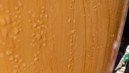
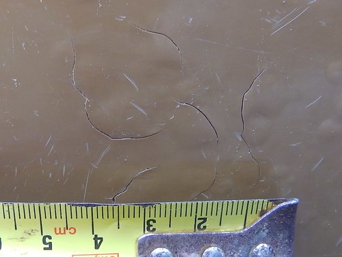
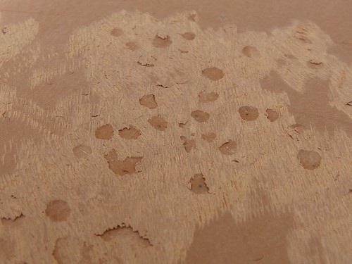
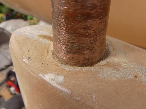
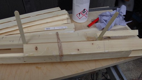
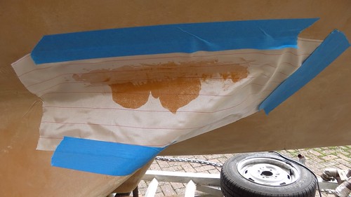
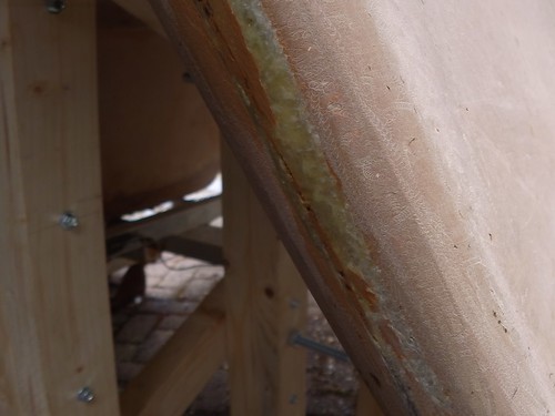
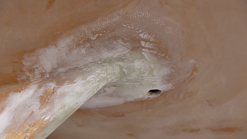
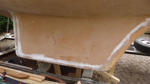
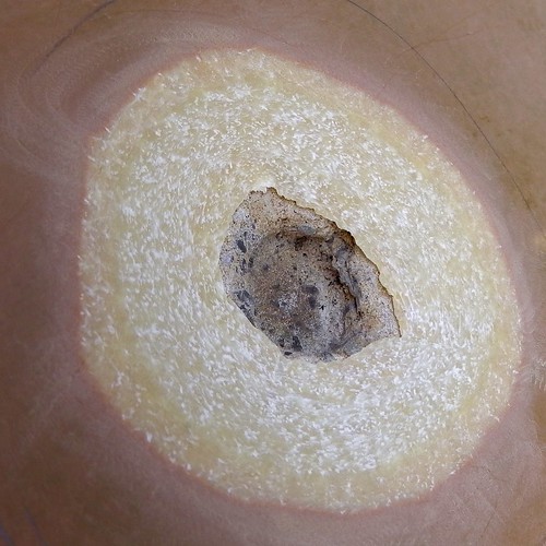
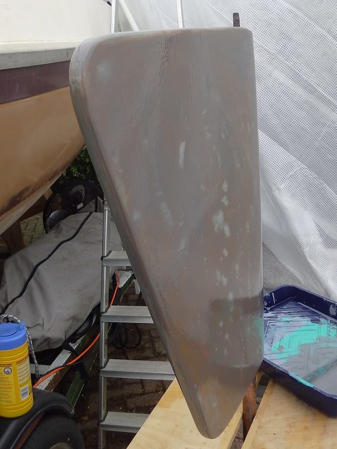
Here’s a picture of the first coat after I rolled it out like a painter.

IMGA0279

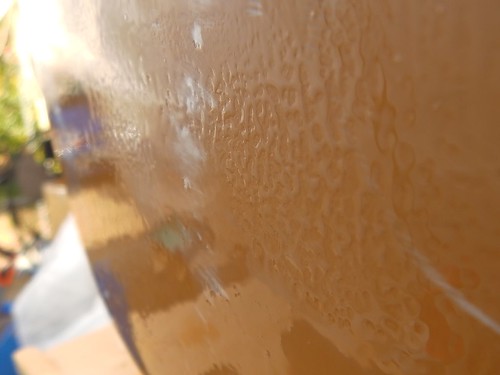
As you can see, the coverage was good in some sections but not in others. This is where I discovered that I could just redistribute it with firm pressure from the roller, and get an even coat.

Don’t use tiny bits of roller. My calculations, based on West Systems manual, suggested that I should use one sixth of a 170mm roller for each coat. OK, I thought, but these small sections started to disintegrate. Later, I used a half roller, and this worked much better.

IMGA0281

Avoid pouring new epoxy on to old, partially-cured epoxy. There’s some sort of reaction that causes the new epoxy to stiffen up fast, reducing working time dramatically. I only had one roller tray available, and while I mixed up the epoxy in a clean disposable plastic cup each time, I poured it onto the left-over tacky epoxy in my roller tray for two of the coats, and then had to hurry to get it rolled out because it was thickening up fast. I ended up finishing the job with a brush because rolling stopped working. After that, I stopped using the tray and used a brush to transfer the epoxy to the surface. When I do the hull I’ll use disposable roller tray covers to avoid this problem. Note that this reaction may be useful sometimes, and it also would seem to imply that the epoxy that you apply over a previous layer might cure faster than the first.

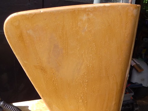
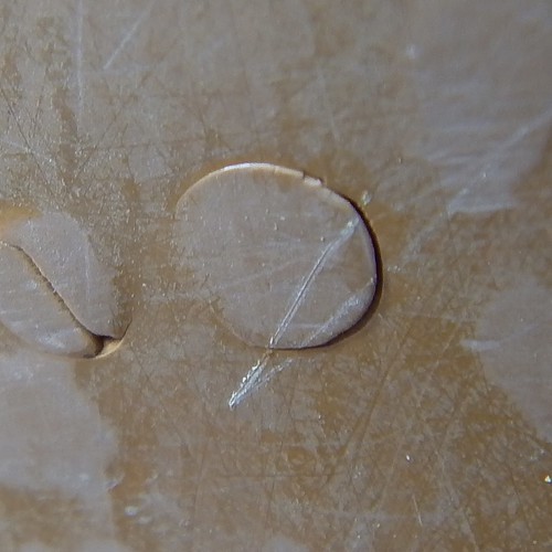
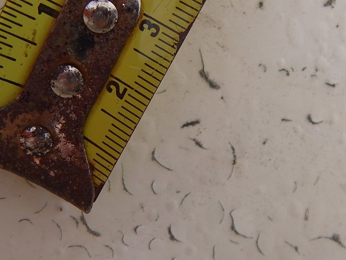
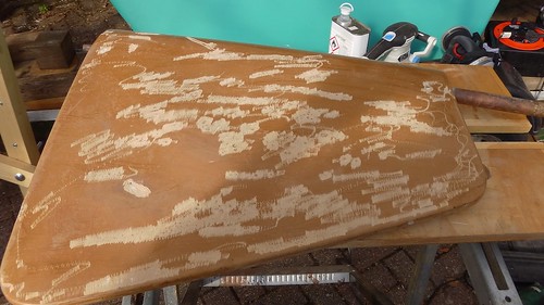
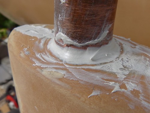
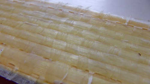
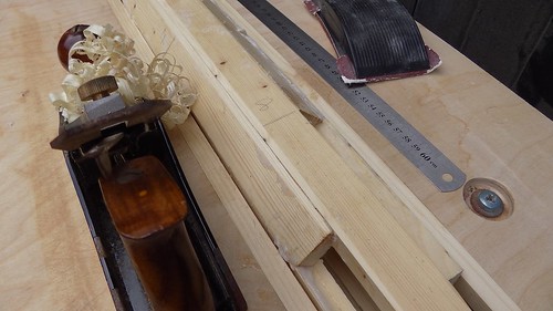
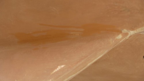
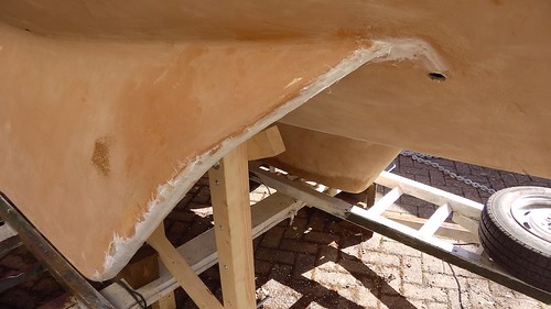
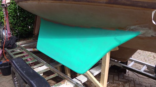
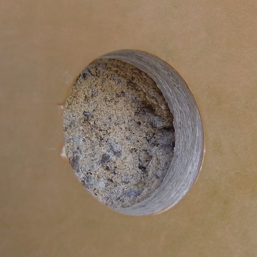
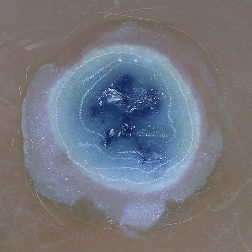
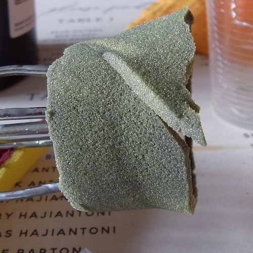
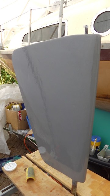
Here’s a picture of the surface after the second layer, which is the first layer containing the barrier coat additive. This layer had the new-epoxy-on-old mistake, but it still worked out OK for the rudder, which is only 0.4m² overall. If I had been trying to cover 2m² (as recommended) I would’ve been in trouble.

IMGA0282

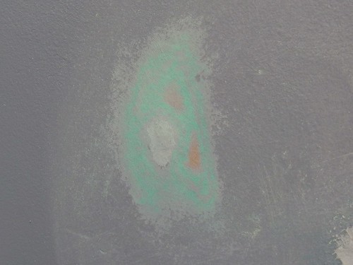
Don’t re-use rollers. If you squeeze them out after use then they seem to stay quite spongy even after the epoxy has set. But I found that the roller contained tiny lumps and flakes which transferred to the next layer. These are harmless, I’m sure, but they will mar the finish. They may introduce flaws that reduce the effectiveness of the barrier.

IMGA0289

Slow epoxy stays tacky overnight. I only managed to get five coats done on the first day, but the temperature overnight was below 5ºC, and in the morning the surface was still a bit tacky. So I was able to apply a sixth layer. This confirms that the slow hardener might save me from failure if I can’t get everything done at once.

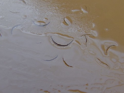
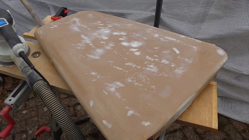
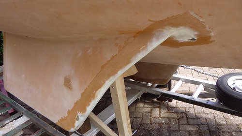
Tipping is easy. This is my first experience with the roll-and-tip method, where you roll out a coat, then lightly go over it with a dry brush or section of dry roller in order to smooth the surface. I thought this would require a lot of skill and a delicate touch, but it turns out to be very easy. Just apply gentle pressure and watch what’s happening and it comes out very nicely.

IMGA0287

In fact, because each layer is translucent, this is a lot like a lacquer. It’s going to be a shame to cover it up with antifouling!

I kept notes as I went, to learn about the curing times. I’ve reproduced these here.

TimeTemp / ºCPumpsNotes
2020-10-09 08:5592Tipped w. half of a half roller. Applied with 1/6 roller. Some excess. Some runs, tipped with brush. Applied too thick?
10:0514still fluid — soaked in to tissue
10:2017gel but fluid
10:4017.5ditto
11:0019just about ready
11:30202Batch went off almost immediately — contact with first batch? Uneven but spread and tipped with brush.
12:0519already tacky gel
12:3017.5still soft but tacky
12:4518ditto
13:0517.5firmer, very sticky
13:3017.52Better than last time but still short working time. Will try clean container.
14:1015Wet and not sticky
14:4512soft and sticky
15:20ditto
16:00122Brushed on from fresh tub and rolled out. Good working time.
18:0012tacky
18:20102
2020-10-10 07:00surface still a bit tacky
07:1552Used heat gun to help spread
19:005Very slight tackiness
2020-10-11 08:0010Surface set but able to dent with fingernail.
2020-10-12 11:0012Can no longer dent with fingernail, but can scratch.
[edit] 2020-10-14Can no longer scratch surface with fingernail.

Finally, I’ll say that this was an exhausting exercise for me. It required attention for a full day with only short breaks. The actual area of the rudder and the physical effort probably don’t matter very much, I think. The concentration required and the inability to rest have left me quite fatigued, with recognizable post-exertional malaise. I will have to think quite hard about whether I can apply this technique to the whole boat with my ME/CFS. Perhaps I can recruit some helping hands for that job. Apply below.

EDIT: I’ve decided that I won’t attempt to apply this barrier to the main hull until the spring for several reasons:

  1. COVID-19
  2. It’ll be easier to schedule in weather with rising temperatures.
  3. Tammy Norie gets extra drying time over the winter.

Thank you for the offers of help. I’ll be in touch.

9 Comments

Filed under Repairs and Modifications, rudder

Craters in the rudder

Most Coromandels I’ve come across have osmosis, where water slowly penetrates the fibreglass and forms blisters that are a lot of work to repair. This is because the polyester resins used in the early 1980s were not very waterproof! I’ve used Tammy’s rudder as a test for dealing with this problem. This article is about the investigation and preparation of the rudder.

I decided to remove the rudder so that I could check everything over and work with it easily while I was getting practice. This was the first time I’d tried and it seemed like a good time.

The rudder is held at the bottom by this bronze gudgeon. I’m pleased to say that the nuts and bolts came apart easily. I wouldn’t’ve wanted to bludgeon my gudgeon.

IMGA0074
IMGA0075

The rudder was now hanging on from the top of its post, attached to the tiller in the cockpit by this bracket.

IMGA0076

After resting the rudder on a wooden block, this also came apart quite easily and I was able to lower the rudder. I then had to jack the back of the boat up with a crane to get it out!

IMGA0078

Time to get a really good look at the surface.

IMGA0174

The rudder had had all the antifouling paint scraped off during the winter, when I very slowly (about 5 minutes per day due to ME/CFS) cleaned up all of Tammy’s undersides. However, I had deliberately avoided sanding the rudder because I wanted to study it carefully and write this article.

On the surface you can see numerous small bumps, and somewhat below the surface there are a lot of vertical streaks. What’s going on? Was this osmosis?

IMGA0177

The bumps are only about 2mm across, and some of them have cracks around them. Extreme zoom time.

IMGA0182

What’s more, if you dig at these they tend to pop out, leaving a conical crater in the gelcoat. However, this crater doesn’t reveal any problems with the fibreglass laminate underneath.

IMGA0183
IMGA0193

These craters somewhat resemble some other craters that appear in the gelcoat on the decks.

IMGA0191

Also scattered around some parts of the deck and the rudder are these crescent cracks.

IMGA0194
IMGA0192

I decided to gather some opinions about what might be going on. These didn’t look like osmosis blisters to me — they’re usually much larger and would show damage underneath. So I made this post on the Practical Boat Owner forums to see if anyone had answers. I had several useful replies with references and experience, and I recommend popping over there to read it. The conclusion was that these were flaws caused by bubbles of water or air caught in the gelcoat during manufacture. Phew! All I had to do was fix up the surface.

My first experiment was to add a layer of epoxy to a small area and see if it would penetrate the cracks. If this worked, it would be an easy way to deal with everything.

IMGA0215

It didn’t work. The epoxy didn’t get in to the cracks consistently, even when I heated it up to make it very runny. So it was time for more drastic action. After quite a few experiments with various tools, I discovered that I could turn the bumps into craters quickly and easily using an oscillating multi-tool.

IMGA0222

The key was to arrange the cutter perpendicular to the cracks around the bubbles. This broke them out immediately.

IMGA0225

Where there was longer cracks, I cut along them to form grooves for filling. The surface of the rudder looked quite devastated after all this.

IMGA0227

While had the rudder out, Blueboatman reminded me to check my rudder tangs — the reinforcing ribs inside the rudder that make it strong enough to turn the boat. Some Coromandels, including Emmelène, have mild steel tangs that rust inside the rudder. Fortunately, it’s easy to check with a magnet.

IMGA0230

I was pleased to find out that Tammy’s rudder is not magnetic. She likely has either stainless-steel or bronze tangs, so I don’t need to worry about rust.

I used epoxy resin thickened to the consistency of soft icing with glass microbeads, and smoothed it over the surface with a spatula. After a couple of days it was hard enough to sand down, making the whole thing very fair.

IMGA0240

While I was at it, I fixed up a few other dents and scratches. For example, I noticed that the material around the top of the shaft was a bit crumbly, so I dug it out.

IMGA0260

And then I made a fillet with epoxy filler.

IMGA0261

This wasn’t my usual self-mixed epoxy. I found these tins of Plastic Padding Marine Epoxy that I bought six years ago. All my other resins became unusable after a couple of years, but I opened up these tins, and after a bit of stirring they seemed fine. I’ve used the mixture for a few non-critical repairs like this one. Seems like good stuff to keep aboard.

IMGA0262

Unfortunately, the rather useless Henkel web site has no technical information about this material.

With everything repaired, I was able to start experimenting with an epoxy barrier. The details of this are quite technical and so I will write about them in my next article. But here’s a preview.

IMGA0287

1 Comment

Filed under Repairs and Modifications, rudder

Sticks with glass and carbon

Thinking about a replacement mast for Tammy Norie has led me to become interested in the mechanics of wood-based composite materials. In fact, I have applications for this beyond building a mast. My plans for a new sail will require a yard, battens, and a boom. It would be most convenient if I could make these cheaply from easily-available materials, so that I can try out variations, and carry and make spares easily.

I did a few small experiments with jointing to make long battens back in 2017, but I didn’t record much information. I mainly concluded that I could make a strong yard, battens, and a boom of any size by gluing smaller pieces with large overlaps.

IMG_20170916_141923

But a mast is much more critical. A mast breakage in the Solent is one thing, but a dismasting when sailing solo in the Atlantic could mean death. I need to know a lot more about my materials.

I have six sticks of softwood, all approximately 33mm × 18mm × 900mm. My plan is to carry out three-point loading tests to determine their properties when modified with composite layers, in particular glass and carbon fibre in epoxy resin. I’ll be measuring changes to elasticity, but also trying to determine yield stress (where they bend permanently) and ultimate (breaking) strength.

My test rig is a car crane capable of exerting over 500kgf. I’m using the legs of the crane to brace the samples, and one of the sticks as a fixed reference. A 100kg spring balance measures the force applied, and a micrometer measures the deflection.

IMGA0233

The spring balance isn’t a very precise instrument, but I am hoping to measure fairly coarse changes in properties, so I’m not too concerned as long as it is reasonably consistent. The steel tube is there to provide a fulcrum for the bending test.

I measured the stick dimensions using the micrometer, and then Dad and I measured the deflection when we applied forces up to about 50kgf. We did this in steps of 2kgf for the first sample. This produced a nice straight line, validating Hooke’s Law and showing that we weren’t passing the yield stress. It also allowed me to calculate the actual Young’s Modulus for the wood at 11.9GPa, somewhat over the guarantee for C16 timber.

Plot of deflection against force for the plain wood samples
Young’s Modulus for the plain wood samples

You can look at the measurements, calculations, and results yourself on this Google Sheet. I’ll be updating it as I go.

In the next step, I modified two of the samples by adding a composite to the top surface. I’m using 600g/m² unidirectional glass, and 200g/m2 unidirectional carbon fibre.

IMGA0244

You might be wondering what this unusual unidirectional stuff is. As the name implies, it has almost all of the fibres running along one axis. For the mast in particular, I’m not very concerned with strength around the mast, but with reinforcing it against bending along its length. To do that, I want most of the fibres running up the mast, for the same reason you run the wood grain in that direction.

The Engineering Toolbox gives properties of unidirectional composites. It also quotes the proportion of resin to fibres. So to lay up the glass and carbon I calculated the mass of the fibres and applied, as best I could, the right amount of resin. It turned out that I needed to mix up about 4g more per sample, though. I noticed that the wood took up a couple of grams, and some amount was lost over the edges and in the mixing cup. I’m working with quite small quantities, so I didn’t expect this to be very accurate.

IMGA0246

I laid up the fibre by first wetting the wood with epoxy, then laying over the fibre, pouring an even bead of epoxy along its middle, and using my squeegee to spread it evenly and push it in to the fibre. I tried to make only two or three passes to avoid overworking the epoxy and introducing bubbles. But I’m not making these samples too carefully. I’m trying to test what might happen to a real mast, whose surface area is about 2.5m², and so I want to apply a realistic amount of attention.

The results after curing aren’t too bad. Here’s the glass, which has come out very neatly. It’s about 0.9mm thick by the micrometer, but the surface is uneven so that’s not all composite.

IMGA0247

The carbon seems harder to keep straight. The tape itself is not perfectly flat before layup, and it’s possible that the slight shrinkage in the epoxy during curing has some effect. I’ve never laid up carbon fibre before so there may be some trick I’m missing. On the other hand, slight waviness in the fibres might help to make the result more elastic and less brittle. I must do some more research on carbon layup. This is about 0.5mm thick by the micrometer.

IMGA0248

Unfortunately, that’s it for now. Storm Alex has stopped all outdoor work for the moment. And it’s probably a good idea to let the epoxy cure for a few days before stressing it.

I can say a little bit about how I might make the mast if this works out well. Let’s suppose that most of the mast’s strength comes from 0.5mm of carbon on its surface. That makes it very vulnerable. A slash with a knife at deck level could bring the whole thing down! Clearly, the fibres need protecting, and it has to be possible to know when there’s been damage.

I will need to wrap the mast in another layer of some sort. That layer must be more elastic than the composite, otherwise it’ll end up taking the strain. It needs to be tough to resist damage. But also, it needs to show that damage. My current thought is to use another layer of fibre running around the mast (increasing elasticity), and to use epoxy pigments to dye the layers in contrasting colours so that wear is obvious to the eye from deck level. But it might be that some sort of elastic protective paint would do the job.

But this does make me wonder whether the fibres can be buried deeper somehow. I found this rather mysterious video of a birdsmouth wooden mast being assembled with some sort of embedded carbon rods.

I am of course not the first person to think of these things. I found this post from Eric Spoonberg in 2004 discussing issues with laying up carbon over wood. He refers to his web site, which is gone, but thank goodness for the Internet Archive, which has preserved this page of interesting free-standing mast projects using composites.

I can also make some predictions of the results. Firstly, there is the Rule of Mixtures, which gives some rather vague bounds using the volumes of the materials. But there is another method using the fact that the materials must all be under the same strain, because they are glued together. In fact, that’s one of reasons that composites work at all.

I’ll come back to this in another post, especially if it keeps raining.

3 Comments

Filed under mast, Repairs and Modifications

So how about a composite mast?

I’ve written about why I need to replace my mast, about wooden mast construction, and in my last article, about how a wooden mast with the same diameter as Tammy’s parners won’t work. Since then I’ve had more than one private message guessing my next move: a composite mast based on a wood core.

As I mentioned in the previous article, the tensile strength of the aluminium alloy in the original mast is probably about 250MPa and it’s in a tube with 3mm thick walls. Basic construction timber has a safe strength of about 10MPa and would need to be 76mm thick to match its strength — bigger than the 50mm available.

Before doing any of these calculations, I was thinking about how I’d coat my wooden mast in epoxy to protect the wood. Then I thought it might be a good idea to sheath it in glass and epoxy for further protection. But, since stresses on are concentrated on the skin, the glass would actually be taking a lot of stress. This is why cored composites work. This video has a nice demonstration of how cored materials behave.

So how about sheathing the mast in layers of glass to achieve the strength while keeping the diameter small?

Once again we can take a look at the Engineering Toolbox to get some starting figures. The tensile strength quoted for unidirectional epoxy fibreglass is 870MPa, however that’s using special S-glass, which has a 40% higher tensile strength than the usual E-glass, so let’s call it 620MPa. That’s still 2.5 times as strong as the aluminium. Furthermore, unidirectional glass mat from East Coast Fibreglass Supplies is made from Jushi E6 320 glass thread, and they quote an experimental tensile strength of 2527MPa in polyester resin, about 10 times the strength of the aluminium!

To be fair, we are not comparing like with like, since the aluminium strength is (I believe) a guarantee whereas the Jushi figures are from testing, but it seems very promising.

Let’s imagine we made a 100mm diameter mast out out of epoxy glass. How thick would it need to be to match the aluminium? (Note: this Python session continues from the previous article.)

seg = 620e6
Ieg = My * y / seg
4.1834724553925743e-07
dieg = (do**4 - (Ieg * 64 / pi)) ** 0.25
0.0977976843453261
teg = (do - dieg) / 2
0.0011011578273369543

That’s just 1.1mm, achievable with a few layers of glass cloth.

Perhaps even more exciting, Engineering Toolbox gives a tensile strength for unidirectional carbon epoxy as 1730MPa. Let’s see how that works out.

sc = 1730e6
Ic = My * y / sc
1.4992791458632348e-07
dic = (do**4 - (Ic * 64 / pi)) ** 0.25
0.09922751849306641
tc = (do - dic) / 2
0.00038624075346679887

A mere 0.4mm. There are, of course, problems.

This is all very well for tensile stress on the upwind side of the mast, but what happens to the equally large compressive stress on the downwind side? Can a 0.4mm layer of carbon take it? How about a 0.4mm layer of carbon that’s stuck to wood? So far, I have not found any satisfactory information for how this will behave.

So it’s time for some empirical testing!

IMGA0233

Here’s my three-point test rig. I have some sticks of softwood. The red object is a car crane capable of exerting half a tonne of force. The stick underneath the legs is being bent upwards by the crane through a 100kg spring balance to measure the force. The metal tube provides a fulcrum. The clamped stick is a reference that I use to measure the deflection, using the micrometer (on the pad).

So far I’ve just done a reference run with one stick, measuring the deflection at 1kgf intervals from about 10kgf to 52kgf. I’m pleased to say the results are very boring.

My plan is to repeat this for each test stick, both ways round. I’ll then laminate one side of a stick with glass in epoxy, and another with carbon fibre in epoxy. Then we’ll test those sticks again (both ways round) and see how much stiffer they’ve become.

I also plan to test some sticks to their yield point, and to destruction, to see how much force that takes. And afterwards it should be quite interesting to see how they failed.

And we can of course calculate the actual Young’s Modulus, yield, and tensile strengths of some of the materials and combinations. This doesn’t mean that every piece of composite will have the same properties, but it should give a good indication.

Watch this space.

Bonus video: Selden winding a carbon mast. At one point there’s a screen showing some useful data.

6 Comments

Filed under mast, Repairs and Modifications

Would wood work?

I don’t trust Tammy Norie’s original mast for offshore sailing. I’ve thought about how I might build a replacement using a wooden birdsmouth construction. But how do I know if my replacement is any more trustworthy? That’s the topic of this article.

Warning: this post contains numbers. Many of them wrong.

I must stress(!) at this point that I am not a professional or experienced engineer of masts, nor a naval architect. This article is about what I have done to try to assess the feasibility of a replacement wooden mast. One of the reasons I’m writing it is that I hope to get feedback where I’m wrong or have missed something. Do not use this article as a guide.

The calculations in this post are written in Python. This makes them easy for anyone to repeat.

Tammy Norie’s existing mast is 8m long, of which about 1.25m is buried beneath the deck. To use terminology from Practical Junk Rig, the Length Above Partners (LAP) is about 6.75m.

L = 6.75

It’s made from a heavily modified aluminium tube with a diameter of 4″ (we’ll call that 100mm) and a wall thickness of 3mm.

do = 100e-3
t = 3e-3
di = do - 2 * t
0.094

For the sake of this discussion, I’m ignoring the part of the mast below the partners, and assuming that the mast is a cantilever beam anchored at the deck. I’m also assuming that the force on the mast is evenly distributed along its length, because that’s a reasonable approximation of the pressure from a sail.

Here’s a diagram of what’s going on in the mast when the boat is heeling.

The wind pressure pushes on the mast. Internal stress within the mast converts this into a twisting moment at the partners, giving a sideways force at the partners and the step that pushes the boat over. What stops the boat from immediatelly falling over is the righting moment — a force that comes from a combination of buoyancy and ballast.

We can draw a similar diagram for when the boat is running before the wind. In that case, the bow of the boat is pushed down and the stern raised. The upshot is much the same though.

There are of course more possible forces than this, especially if the boat is oscillating, or has been knocked down and has its mast in the water. But here I am working towards some basis for comparison between masts, as you’ll see.

I believe we can use all the standard engineering formulae that apply to a cantilever beam, such as those provided by the excellent Engineering Toolbox. (And of course these match the fomulae I find in my dad’s engineering books first published by the Victorians!)

Here’s a useful diagram from Engineering Toolbox. In this case, L is the LAP, A is the partners, and B is the mast head. q is the wind force per unit length.

Now we can do some calculations. Suppose there is a wind force on the sail of 1000N, approximately 100kgf.

w = 1000
q = w / L
148.14814814814815

How much should Tammy’s mast bend? First we need to get E, the Young’s Modulus, and I, the moment of inertia. Engineering Toolbox gives us a Young’s Modulus for 6062T6 aluminium alloy of 68.9GPa. I’m assuming 6062T6 because it’s commonly used for masts, but I can’t be sure that’s what Tammy Norie’s original mast is made of.

E = 68.9e9

We can also calculate the moment of inertia for a hollow tube like this:

from math import pi
I = pi * (do**4 - di**4) / 64
1.076246025868629e-06

Now we can calculate the deflection

d = q * L**4 / (8 * E * I)
0.5184305059991821

giving just under 52cm. From my observations of Tammy Norie’s mast, this seems about right. This gives us some confidence that we’re on the right track. We also want any replacement mast to deflect by a similar amount, and that will help us decide the material and the diameter.

But how strong is Tammy’s mast? Well, the maximum stress on the mast happens at the partners. In fact, it happens at the outside skin of the mast at the partners. (And this is why we don’t want holes near there.) We can calculate the stress from the moment at the partners, M, and the radius of the mast.

y = do / 2
0.05
M = q * L**2 / 2
3375.0
s = y * M / I
156795004.06405988

That gives a stress of 157MPa for our example force on the mast. But we can rearrange this formula to get a maximum force instead.

When a material like aluminium is stressed, it stretches (or compresses), but when the stress is removed it returns to how it was, as long as the stress is less than the yield stress. Of course, we do not want our mast to permamently bend (or break). We can look up the yield stress of 6062T6 aluminium alloy as 241MPa.

sy = 241e6
My = sy * I / y
5187.5058446867915
qy = My * 2 / L**2
227.70944722904983
wy = qy * L
1537.0387687960863

That gives a moment that could cause the mast to bend permanently, My, of 5188Nm, and a wind force, wy, of 1540N, or about 154kgf. That doesn’t seem like an awful lot! That’s about the weight of one human standing on the end of the mast if the boat were on her side.

I do not know the correct righting moment for Tammy Norie, but Selden’s righting moment calculator gives an estimate of 4100Nm. That seems a little tight, but it does mean the wind shouldn’t be able to bend the mast before knocking Tammy over sideways, though it might well be able to dismast me on a run.

As an aside, I’ve sailed Tammy downwind under full sail in a force 7 wind. That’s about a 16m/s wind, which we can plug in to a wind force formula using her sail area of 18.3m², assuming a flat-plate drag coefficient of 2.0.

v = 16
SA = 18.3
P = 0.613 * v**2
156.928
f = SA * P * 2.0
5743.5648

This suggests that Tammy Norie’s actual mast has been under a wind force of 5740N, nearly four times the safe yield limit for the aluminium.

Now, what if we want to build a birdmouth wooden mast, as I described in my previous post in this series? We should be able to use these calculations to work out if we can make a mast that’s at least as strong as Tammy’s 3mm aluminium tube.

It’s a bit tricky to get engineering figures for wood. There are standards for construction timber, such BS EN 388 which specifies certain properties. For example, it says that C16 timber has a safe tension load of 10MPa and a safe compresive load of 17MPa.

What if we used the safe figures promised by BS EN 388? What if we built the mast out of really cheap C16 construction timber? It needs to withstand the same moment, My, as the aluminium mast.

sc16 = 10e6
Ic16 = My * y / sc16
2.5937529223433962e-05
dic16 = (do**4 - (Ic16 * 64 / pi)) ** 0.25
ValueError: negative number cannot be raised to a fractional power

What does this mean? Well, there is no inside diameter that works. Even a solid C16 mast wouldn’t guarantee to be as strong as the aluminium tube. Boo! In fact, we can calculate the minimum stress requirement for a solid mast to match the aluminium.

Isolid = pi * (do**4 - 0) / 64
4.9087385212340526e
ssolid = y * My / Isolid
52839500.640000045

This gives a minimum yield strength of 52.8MPa, and there is no wood class that guarantees this. Tammy Norie’s 100mm mast is just too slim!

So what would the outside diameter of a C16 wood mast need to be?

doc16 = (Ic16 * 64 / pi) ** 0.25
0.15161412929775825

That gives an outside diameter of 152mm. As it happens, the inside of a cylinder doesn’t really do all that much, because the stress is concentrated at the surface. So we can calculate that if the wood were 50mm thick, the diameter would still only need to be 153mm as that still gives a stress under 10MPa.

I50 = pi * (0.153**4 - 0.053**4) / 64
2.651164514924116e-05
s50 = y * My / I50
9783447.64250753

For comparison, in Practical Junk Rig, Haslar and McLeod give a formula for calculating the diameter of a wooden mast with thickness that is 20% of the diameter. They don’t give a derivation of this, but here’s how it works out, based on Tammy Norie’s sail area of 18.3m².

SA = 18.3
doPJR = (L + 2 * SA**0.5) / 85
0.18006705711156443

So that gives an outside diameter of 180mm and a thickness of 36mm. That seems chunky even for cheap wood! We can plug this result into our engineering formulae to calculate the stress such a mast would create.

diPJR = doPJR - 2 * (doPJR * 20/100)
0.10804023426693865
IPJR = pi * (doPJR**4 - diPJR**4)/64
4.49185623973911e-05
sPJR = y * My / IPJR
5774345.3572638

So PJR’s mast would stress its material by only 5.77MPa when under circumstances that would cause the aluminium mast to yield. Quite a safety margin.

Arne Kverneland, a well known junk rig builder, says in his chapter on wooden masts, that PJR’s formula

… has proven to be very conservative unless you rig with a SA/disp. of around 14. More often than not, it will result in over-strong and heavy masts. … On a little boat, any SA/disp. below 20 is for chicken.

He calculates a mast diameter from the displacement of the boat, reasoning that the sail can always be reefed. Indeed, that’s one of the great advantages of the junk rig, and I too, am planning an increase in sail area. Tammy Norie has a notional displacement of 908kg, and salt water has a density of 1025kg/m³, so we can work from there.

m = 908
SAAK = 14 * (m / 1025.0) ** (2.0/3.0)
12.913263838140487
doAK = (L + 2 * SAAK**0.5) / 85
0.16396477655941352

So Arne’s formula suggests an outside diameter of 164mm. Let’s work out what stress that causes.

diAK = doAK - 2 * (doAK * 20/100)
0.09837886593564811
IAK = pi * (doAK**4 - diAK**4) / 64
3.0880976663585186e-05
sAK = y * My / IAK
8399193.298189778

So Arne’s mast would cause a stress of 8.40MPa at the yield moment of the aluminium mast — a reasonable margin under what is promised by our cheap C16 timber.

Of course, that’s still way below what the timber will actually bear in practice. To illustrate this point, let’s look at an average tensile strength for wood. The US Department of Agriculture publishes a very extensive list of properties in “Wood as an Engineering Material”, but even it says

Relatively few data are available on the tensile strength of various species of clear wood parallel to grain.

But it does have a few sample figures in its table 5-7, “Average parallel-to-grain tensile strength of some wood species.” Sitka spruce is often used to build boat spars, and it gives an average tensile strength as 59.3MPa.

sw = 59.3e6
Iw = My * y / sw
4.373950965165929e-06
diw = (do**4 - (Iw * 64 / pi)) ** 0.25
0.057451695315429104

So even with a 100mm mast, this gives an inside, diw, of 57.5mm, or a wood thickness of 21mm. I will repeat that this is based on average breaking stress figures for the wood, compared with minimum yield stress figures for the aluminium, so I wouldn’t trust this.

So, what is the conclusion from all this?

A trustworthy offshore purely wooden mast for Tammy Norie is feasible, but probably only if I increase the diameter of my partners. That’s not terrible, since Tammy has quite a large 150mm aperture at the level of the partners beneath the mast cone.

IMGA0199

Still, I’d rather not start cutting.

So what about an impurely wooden mast? This will be the topic of my next article.

IMGA0219

19 Comments

Filed under mast, Repairs and Modifications

Ascending bird experiments

Tammy Norie’s original mast has suffered some damage, and has a number of possible weaknesses (a hinge, holes) that make me reluctant to trust it for sailing offshore. So I started thinking about how I might build a replacement.

Since I don’t have the facilities at home to extrude aluminium or forge steel, the obvious choice is wood, though as you will see later in this series, composites such as fibreglass or carbon/exoxy are not out of the question.

There are a number of ways to construct a mast out of wood. Quite a few are covered by Haslar and McLeod in the excellent Practical Junk Rig, chapter 8. The most obvious is to find a piece of mast-shaped wood from a single tree! Aside from the difficulty in sourcing a mast this way, there are all sorts of problems with knowing that your mast is strong and reliable; it’s hard to inspect the inside of a tree trunk. The mast would also be solid and heavy.

By building a mast from smaller pieces of wood, we can form a kind of composite. The smaller pieces can be inspected and tested. Imperfections and flaws can be distributed randomly, reducing their impact. And the grain of the wood can be turned in different directions, reducing the chance of fracture or warping.

There are quite a few possible ways of doing it. I recommend a look over the article “Wooden Mast and Spar Building”, which has useful diagrams.

The method looks best to me is the modified birdsmouth, and in particular the octagonal version, where 45º cuts are made along the edge of planks to allow them to join together in an octagon. The outside of the octagon can then be smoothed into a circle — important for distributing chafe and load.

Modified octagonal birdmouth section

I decided to try this out. These cuts would be tricky to make by hand, so I ordered a birdsmouth router bit. Not having a suitable router, I jury rigged one using my dad’s pillar drill and a temporary fence.

IMGA0965

I used this to make birdsmouth cuts along the edges of some cheap 34mm × 18mm softwood.

IMGA0967

Altogether I made 16 staves so that I could try out jointing ideas. An important thing here is that I deliberately did not make them accurately. In my mind, I could see that the birdsmouth arrangement should compensate quite well for defects and inaccuracies, and I wanted to test my theory. It’s very useful to have a forgiving construction technique, especially when you’re an amateur woodworker.

The pieces are really nice to handle, and very easy to assemble. With just a little pressure the octagon holds together very firmly with no play. An elastic band is plenty to keep a model together for experiments.

IMGA0089
IMGA0969

There are several videos showing birdsmouth spar construction. One I particularly recommend is “A Whisker Pole for Julia”.

If you watch that video or read more about this method of construction, you’ll notice that it requires the staves to be as long as the finished spar. In some cases that means buying long planks, and in others the builder scarfs together planks in order to create long staves. This makes sense, but it creates a few difficulties:

This is where my real experimentation starts. I wonder whether it’s possible to create an indefinitely long spar in sections. I had sat around imagining various schemes, and now I had the parts to try out a few.

The basic plan was to assemble one section (a set of eight staves) in such a way that another section could either be joined to it, or assembled on its end. This process could then be repeated to create a long spar. This would naturally limit the amount of surface that needed gluing, end each section could be aligned and glue allowed to cure before the next is added. This reduces the complexity of assembly, the cost of the wood, and the urgency of the assembly process. (This last one is particulary important if you have ME/CFS and might collapse at any moment.)

Clearly, if you just create two sections with flat ends and attempt to butt them together you’re going to fail. You’re entirely relying on the glue, and a mast comes under a lot of bending force and all that stress will be concentrated on that glue. Fortunately, the fact that we have eight independent staves lets us stagger the joints.

So, what if we crenelate the staves, so that alternate staves interlock with the next section? Here’s a picture of that.

IMGA0968

I tried this. It’s very nice for construction, but it is remarkably weak. Using elastic bands to hold the octagons together is a way to simulate weakness in the glue or wood. This crenelated joint still has four aligned butt joints, and is far too wobbly and weak. I was able to break it apart with a mild bending force using my hands.

One of my other thoughts was to use a helix, rather like a spiral staircase. Why not just glue the staves on one at a time in a helix, building a stairway from the deck to the mast head? It’s an appealing notion, but it doesn’t work at all well. You end up constructing what is essentially a spiral fracture in the mast, making it very easy to unravel with a bit of torque. I don’t have a photo of this because it’s actually quite hard to get it to hold together at all!

Then I realized I could arrange to have no two joints in line by combining the crenelation and helix, creating a double helix. This is a bit tricky to visualize. It’s what is going on in this photo.

IMGA0970

It’s a lot simpler to see if I show you a diagram of how the staves would look if unrolled.

Unrolled double-helix arrangement of birdsmouth staves

I tried this method with my staves, and the joint was very stiff indeed. It would not budge at all, either to bending or twisting forces.

In addition, I found that the two sections would naturally align very accurately when squeezed tightly. I have a geometric intuition about why this might be that I find hard to explain, but I’m hopeful that it would be very helpful when assembling a long spar from sections.

All of this was done before my latest ME/CFS relapse, so many months passed before I was able to make progress. In the past few weeks, though, I have done a bit more.

I have slowly been watching the construction of SV Tapatya, a Benford dory similar to Annie Hill’s famous Badger. Tony decided to eschew epoxy for the main construction and use a urethane foaming glue called Collano Semparoc 60. He discusses why in this video from his building series.

Tony has also carried out some experiments with Semparoc and plywood, boiling and soaking to see if he can get it to weaken. I like this kind of thing!

I thought that Semparoc might make a good glue for building a mast, mostly because of the ease of handling. Aside from toxicity problems, epoxy has to be made up in batches. I read one article about birdsmouth construction where about 20 friends were needed to apply the epoxy in time to get the mast together! Well, my section construction method could help with that, but it could also be helped by easy gluing.

I bought a tube of Semparoc to try out, and used it to glue together a section using my prototype staves.

Firstly, I marked off the double helix offsets a bit more carefully.

IMGA0092

Then I parted the joints using two lolly sticks and squirted in the Semparoc straight from the dispenser.

IMGA0093

As Semparoc cures it foams, reacting with the moisutre in the wood, and filling gaps. This is again important so that perfect cutting accuracy is not required.

IMGA0096

Once the glue cured, I planed off the corners of my octagon to make a somewhat irregular decahexagon.

IMGA0098

I think it’s interesting to look at the joints after planing, which slices some of the foam open.

IMGA0099

This does not seem to make the glue weak (it’s a well tested glue) but it could allow moisture to settle, and might need careful sealing. Mind you, so does the rest of the wood.

The result was this rather nice object, which is also strangely cuddly.

IMG_20200909_081459

And here it is with the staves of the second section slotted in place, but not glued. (You’ll need to click through to look at it in detail.)

IMGA0197

That’s as far as I’ve got so far in building anything. There are a few obvious refinements, such as arranging some sort of interlocking on the end of each stave. I don’t think a full 12:1 scarf is necessary, but something simple might be wise.

For further reading, I highly recommend Duckworks‘ article “Birdsmouth… and Other Wooden Masts and Spars” and also all of the other articles on birdsmouth on the Duckworks site.

The most obvious next question is whether a mast made like this is strong enough overall for Tammy Norie! That will be the subject of my next article in this series. But the answer is no. Or maybe. You’ll see…

14 Comments

Filed under mast, Repairs and Modifications

Scratches and holes in the mast

I recently promised that I’d write about my plans for a replacement mast for Tammy Norie. This is quite a big and complicated topic that I’ve been thinking about for a long time, so it’s going to be a series of shorter articles.

This one is about the problems with the existing mast, and why I’m considering making another.

In August 2017 I noticed that my mast had gained a lot of surface damage, as you can see in this photograph. Ironically, this damage was caused by the screws holding in the anti-chafing strips on the mast and battens. You can see more details in my post, “Little jobs roundup, 2017-09”.

IMGA0618

I started a thread on the Junk Rig Association technical forums to ask for advice, and my conclusion was that I should polish these out to avoid mode 1 fractures that could propagate through the whole mast. Stress on a beam (such as a mast) is concentrated on the skin, and the molecular bonds can unzip if they’re given a start.

However, this thread revealed other problems. David Tyler, a former engineer of masts, rightly criticised my drilling of a hole near deck level to secure the mast sleeve, and even comissioned this cartoon for the magazine!

But that wasn’t the end of it: I realised there were at least seven more holes. This one is exactly at deck level.

IMGA0193

And there are six more rivet holes that support this collar, which itself holds up the mast sleeve.

Tammy Norie's mast has too many holes at deck level.

We discussed various of mitigating the problems in the thread, and I may work on them, but this was really the final straw for me. I do not feel I can trust Tammy Norie’s original mast for long distance sailing. Getting dismasted near the coast is one thing, but on a long voyage I need to be more sure of my boat.

Commissioning an expensive new mast isn’t really in the Tammy Norie spirit. Roger Taylor’s lamp post solution could work, but it would involve cutting the boat around, making it impossible to swap back to the old mast for bridge-ducking coastal sailing. Instead, I started thinking about ways that I could build a new mast myself, and that will be the topic of the next article in this series.

3 Comments

Filed under mast, Repairs and Modifications

Keel seam reinforcement

I’ve often wondered how Tammy Norie’s hull was moulded. She has twin keels, and that would seem to makes her hull impossible to free from a mould. Stripping and sanding her bottom ready for osmosis prevention revealed the answer: the hull was made in two parts.

There’s a seam that runs around the edge of each keel, then down and across the hull to the other keel. A saddle-shaped section of the hull, together with the inside wall of each keel, must have been moulded separately then joined to the rest of the hull. The main part would’ve included the outside wall of each keel and otherwise had a large hole in the middle. You’ll be able to see this seam in some of the pictures below.

On the hull this seam appears very sound. There’s no sign of it on the inside of the hull at all, suggesting that the middle section was united with the rest at an early stage of laying up fibreglass. The seam on the hull isn’t very fair in some places, leaving a ridge of about 1mm.

On the keels, though, this seam looks very dodgy. I first noticed it when I was repairing a hole I knocked in the starboard keel. Looking at it with all the antifouling removed, it look as if there wasn’t a lot of glass fibre crossing at all, especially underneath.

IMGA0051

As you’ll see, this was confirmed when I started working on reinforcement. Given that the concrete inside the keels is not well bonded to the keel walls, it’s not entirely clear what’s holding the keels together!

With the hull cleaned up in preparation for an osmosis barrier, I decided now was the time to reinforce them.

I outlined my plan to the nice folks at East Coast Fibreglass Supplies and they recommended laying up layers of biaxial cloth over the seam. From them I bought 10m of 450g/m² biaxial glass tape, 5kg of polyester resin, and various supporting bits and pieces.

But the first problem was how to gain access to the keels. My usual method involved using my dad’s car crane to lift Tammy Norie using ropes crossed under the hull to the cleats. But these ropes press against the keels. So I came up with the idea of building a kind of crutch that would fit in Tammy’s “armpit”.

I started with some CLS C16 construction timber from the local B&Q, which I doubled up using long screws.

IMGA0008

I made up four of these and cut them to length to fit under Tammy. You can see here how the red crane is lifting her over. At this stage, for safety, I always avoid crawling underneath the boat, even though she’s on both a crane and a block.

IMGA0009

Since Tammy is curved, I measured the lengths of the four pillars as best I could, taking account of how they’d need to avoid the trailer axles. Then I laid out the crutch and assembled it on the trailer.

IMGA0010

I used coach bolts to attach diagonals to ensure that the pillars couldn’t shift fore-and-aft.

IMGA0013

You might be surprised to hear that this object still flexes! This was an accident, but turned out to be useful when manoeuvring the crutch into place.

IMGA0015

I carefully lowered the boat onto the crutch and used wedges to ensure that there was reasonably even pressure on all the pillars.

If you’re interested in the calculations, CLS C16 timber guarantees a safe compressive load of 16MPa. My pillars are 76mm × 63mm, giving 0.076 × 0.063 × 16000000 ≈ 77kN or 7 tonnes of support each. Tammy Norie weights about 1 tonne total. I now felt reasonably safe crawling under the boat!

IMGA0017

I was now able to get to work cleaning up and reinforcing the keel seams.

First of all, the root of the starboard keel showed some stress cracking in the gelcoat. You can also see the seam quite clearly here. The hole is where I’d removed the sink drain seacock.

IMGA0021

I investigated these cracks by using an oscillating multi-tool to grind away the gelcoat.

IMGA0024

This revealed no cracking in the fibreglass underneath, so I was free to fill and forget. The process I used was similar to that demonstrated in this excellent BoatworksToday video.

As an experiment, I filled this crack with some gelcoat, which I tinted with a pigment I’d selected to match the hull.

IMGA0039

After sanding, the match wasn’t too bad! I’m trying to get a match close enough to make repairs on visible parts of the boat, so this is a useful trial.

IMGA0049

Using the oscillating multi-tool, I worked along the keel seam, removing the paper-thin gelcoat and the tenuous, void-filled fibreglass behind it.

IMGA0027

The aft seam wasn’t nearly as bad, though the gelcoat was so thin that it rubbed away with light sanding.

IMGA0029

After cleaning everyting up, I worked around the keel in sections. Firstly, I filled the forward seam with a mixture of polyester resin, glass microbeads, and chopped glass for a bit of strength and stiffness. It’s fascinating adding chopped glass to resin. Even though there’s no chemical reaction between the glass and resin, the two together become slimy, resembling egg white. (Later, I bought some West System 404 high density filler, which would’ve been better.)

IMGA0056

After a bit of sanding to clean up, I added a second layer of filler, and while it was still soft, added a strip of biaxial glass cloth, pre-soaked with polyester resin. I smoothed this over the leading edge of the keel to get a good shape to the glass, pressing it with a paddle roller. The squishy filler combined with the cloth surface allowed me to get a nice rounding.

IMGA0058

I repeated this process underneath the keel, resulting in a nice horizontal surface.

IMGA0061

And then once more on the aft edge. Each of these sections of glass tape overlapped, meaning that the vulnerable forward and aft corners of the keel now had two extra layers.

The biaxial cloth has most of its fibres at the two 45° angles, but is held together with some glass stitching along its length. This stitching is quite prominent once the glass has set. And in my inexperience I wasn’t sure what to do about it. So I did some experimental filling along the forward edge of the keel, experimenting with pigmented filler. But it turns out this wasn’t really necessary. There’s no harm in sanding the cloth flat as this only removes the stitching, and that’s only there to keep the tape together while you’re laying it up.

I added a second unbroken strip of glass tape all the way from fore to aft, with the help of an extra pair of hands from Dad. Then I sanded, faired the edges, and sanded again. Here’s the result, which looks a little messy, but is firm, strong, and smooth.

IMGA0065

This work has the added benefit of reinforcing the roots of the keels. Here’s the forward root after fairing and sanding. The fairing was done with polyester resin containing glass microbeads.

IMGA0066

I was considering using International Gelshield 200 as an epoxy-based osmosis-prevention layer for the entire hull. I bought the smallest tin to give it a trial run on the keels. It’s expensive stuff.

IMGA0110

I calculated that 60ml of the base, with 20ml of the hardener, would be enough to cover the keel. Gelshield is quite nice to work with, and rolls on like paint. It dries to the touch within an hour, allowing multiple coats to be built up.

IMGA0111

I bought a tin of the green version, which you’re supposed to use alternately, so that you know you’ve made a completely sealed coat. This stuff is a really nasty colour!

IMGA0112

And then after three more coats over the course of an afternoon, the keel was done.

IMGA0114

Now, I have a warning about Gelshield that is not in the instructions. It’s clearly made out of two different materials: a paint (it smells like paint solvent) and a two-part epoxy resin. The paint dries quickly, which is convenient, but the epoxy does not harden for quite a while. I was easily able to dig a hole right through with my fingernail 24 hours later.

IMGA0115

But after another 24 hours the stuff was too hard to mark with my fingernail, and I could put the boat down on her keel and start work on the port side.

The port side keel went much the same, except here the seam wasn’t so bad, and instead there was a lot of surface damage. My fault, no doubt.

IMGA0123

The only problem I had on the starboard side was a sudden unexpected increase in temperature. On one day the temperature went up from 20℃ to 30℃ in about half an hour, causing all my filler to harden, and wasting one whole strip of glass tape. After that, I made up all my polyester with less catalyst, prefering waiting to wasting.

Here’s Tammy at the final stage, just before adding the barrier coat to the port keel. It gives you some idea of my working environment.

IMGA0157

She’s looking a bit rough. I have work to do!

5 Comments

Filed under hull, keels, Repairs and Modifications

Draining the keels

At the end of last year I made a plan to investigate whether there was water trapped inside my keels. Well, there was. Lots. Here’s the story of how I got most of it out.

One of the things I did last year was to drill a few investigative holes in to the top of my keels, from inside the boat. I was keen to find out if there were large voids. If there were, I thought they’d likely have accumulated water, but also, I wondered about making use of the voids. There are more details about this in my earlier post.

It turns out my keels are filled to the top with something very sandy. I made several holes in the tops of both keels and they all came up with the same material.

IMG_20191228_112949

Here’s a closer look at what came out.

IMGA0950

I certainly didn’t find any voids. Although this ruins any plans for clever water tanks, it also keeps things simple. I will just fill the holes and leave them alone!

However, I also drilled some exploratory drain holes in the bottom of the keels, and in particular, the port keel let out a great deal of water.

IMGA0980

By the time this stopped flowing I had about two litres in a bucket, and still more was dripping. The water smelled slightly of polyester, suggesting it had already been dissolving the boat a bit.

After a couple of weeks the water had stopped dripping, but the holes were still wet to the touch, and poking into them with a stick revealed quite a large void still containing water. I used an air compressor to blow air in to one of the holes, and this forced water out of the others. I also noticed that it caused the side of the keel to bulge outwards slightly. Clearly, whatever was in the keel was not attached to the laminate! I thought it was very likely that a lot of water was trapped in a layer inside, and was not going to leave of its own accord: gravity wasn’t going to move it, and there was no air flow to evaporate it.

So I decided to create some air flow. I found the top of where the bulging occurred, in the middle of the keel wall, and drilled much larger hole to see what was inside.

IMGA0982

We can see more of the sandy substance I pulled from the top of the keel, but here it is fairly cohesive and contains larger grains. I suspect it’s a loose form of concrete. There should be some heavy metal encapsulated in it somewhere, for ballast.

You can also make out a bit of a gap between the laminate and the concrete. This is where a lot of water was trapped. I bodged together a way to seal a socket for the air compressor into the keel.

IMGA0986

Then we led a hose to the air compressor that is also aerating my parents’ fish pond!

IMGA0989

With the compressor running, a lot more water was forced out of the holes in the bottom of the keel. The compressor runs for many hours each day, and I left this whole thing set up for sevearal weeks. After a week there was barely any water, and after two more the holes were dry.

IMGA0032

Meanwhile, the starboard keel was not leaking water from the bottom, but did sound hollow in places when tapped with a hammer, so I decided to drill some holes to investigate.

IMGA0084

I poked a dry cotton bud into each hole to see if there was any moisture. There was a little, but no liquid water that I could find.

IMGA0083

At this point I had a decision to make. How far should I take this drying process? My intention was to remove water that might cause osmosis blistering and delamination. I was planning to coat the whole bottom of the boat in an impermeable barrier, and although moisture in most of the hull would be able to evaporate inside the boat, this could trap it permanently inside the keels, where it could form osmotic blisters.

But I couldn’t really see how I could take the drying process further without some much more serious destruction, such as cutting away the sides of the keels. That’s the sort of rebuilding that I would have to do anyway if I got serious osmosis, and doing it now was going way beyond prevention. It was more like a premature cure.

So I decided to stop at this point. The keels weren’t perfectly dry, but they were certainly much drier. I’ll have to keep an eye on them.

As an experiment, I wondered if I could fill one of the voids with some thickened polyester resin. I made up about 100ml in a syringe and injected it into one of the holes. This is loosely based on the process recommended in West System’s excellent “Fiberglass Boat Repair & Maintenance” (chapter 5) for fixing delamination.

IMGA0105

It just vanished. I suspect the voids are large and that attempting to fill them with resin would be pointless and expensive.

So I plugged all the small holes with thickened polyester resin, and set to work to repair the large hole in the port keel, using the usual method. First I ground a slope into the laminate to provide a good bond for new material. You can also get a good view of the concrete in this picture.

IMGA0152

I filled the hole in the concrete with a thickened polyester resin mixed with chopped glass fibres. On top I laid up alternating layers of chopped strand and woven glass mat in polyester resin. There are plenty of guides and videos on this process available (I recommend BoatworksToday) but I think the result is quite interesting. You can see the edges of the woven layers in the rubbed-down fibreglass.

IMGA0159

Finally, all of the holes, patches, and other damage were covered up by further layers of glass and epoxy barrier coatings. That’s described in my later post, “Keel seam reinforcement”. But here’s a sneak preview.

IMGA0114

11 Comments

Filed under keels, Repairs and Modifications

Tammy’s twenty twenty

It’s been nine months since my last post. ME/CFS has kept me from making a great deal progress on Tammy Norie. That, and the COVID-19 pandemic have kept Tammy out of the sea this year. Most of my plans for this year were scuppered: meeting three other Coromanels, sailing to Brittany, and attending the International Maritime Festival in Brest (sensibly cancelled). Disability also kept me from writing.

In the past month I have improved a great deal, and made quite a bit of progress, and I find I have quite a lot to write about!

  • I built a third tent for Tammy Norie that helped to dry her out thoroughly over the winter.
  • I have scraped and sanded all of Tammy’s bottom back to the bare gelcoat (and through it in some places) in preparation for an osmosis-preventing barrier.
  • I discovered water inside Tammy’s keels, and have been through a quite unusual drying process!
  • I found weaknesses in the seams around Tammy’s keels, and reinforced both keels with quite a bit of new fibreglass.
  • I have made a start on the closed-cell foam insulation and floatation and can show some details.
  • I have built a prototype for a mast replacement, and have detailed plans to build a complete new mast.
  • I am finally enlarging the cockpit drains, reducing the draining time from around 40 to just four minutes.

I hope to write posts about all these topics, with many pictures and details, in the coming days. Watch this space.

4 Comments

Filed under antifouling, cockpit drains, hull, keels, mast, Repairs and Modifications