Category Archives: mast

Sticks with glass and carbon

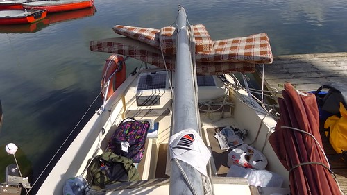
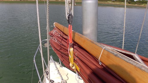
Thinking about a replacement mast for Tammy Norie has led me to become interested in the mechanics of wood-based composite materials. In fact, I have applications for this beyond building a mast. My plans for a new sail will require a yard, battens, and a boom. It would be most convenient if I could make these cheaply from easily-available materials, so that I can try out variations, and carry and make spares easily.

I did a few small experiments with jointing to make long battens back in 2017, but I didn’t record much information. I mainly concluded that I could make a strong yard, battens, and a boom of any size by gluing smaller pieces with large overlaps.

IMG_20170916_141923

But a mast is much more critical. A mast breakage in the Solent is one thing, but a dismasting when sailing solo in the Atlantic could mean death. I need to know a lot more about my materials.

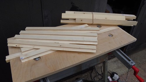
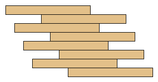
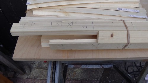
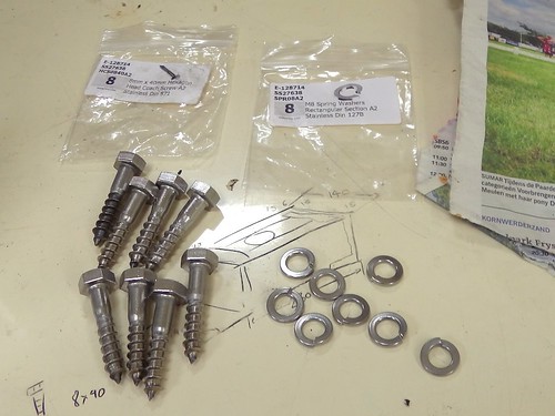
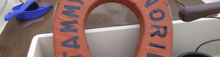
I have six sticks of softwood, all approximately 33mm × 18mm × 900mm. My plan is to carry out three-point loading tests to determine their properties when modified with composite layers, in particular glass and carbon fibre in epoxy resin. I’ll be measuring changes to elasticity, but also trying to determine yield stress (where they bend permanently) and ultimate (breaking) strength.

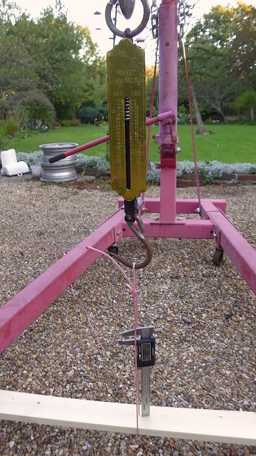
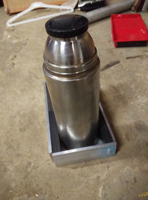
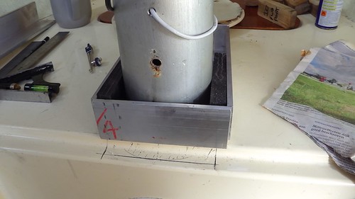
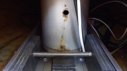
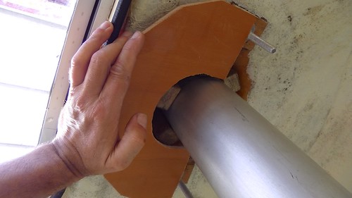
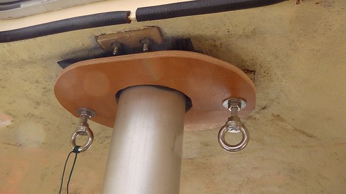
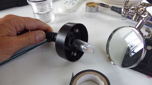
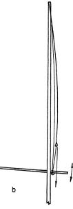
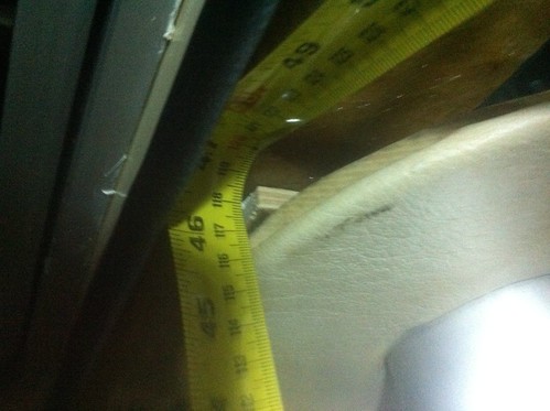
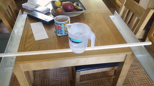
My test rig is a car crane capable of exerting over 500kgf. I’m using the legs of the crane to brace the samples, and one of the sticks as a fixed reference. A 100kg spring balance measures the force applied, and a micrometer measures the deflection.

IMGA0233

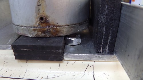
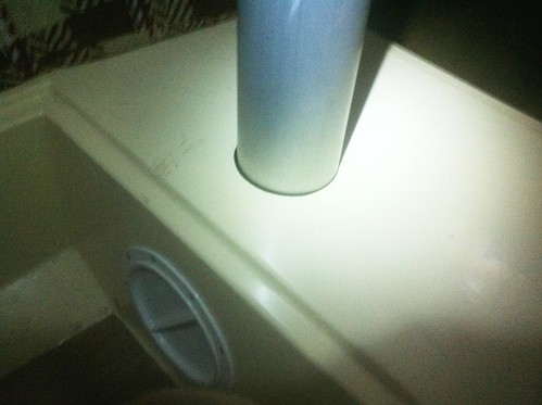
The spring balance isn’t a very precise instrument, but I am hoping to measure fairly coarse changes in properties, so I’m not too concerned as long as it is reasonably consistent. The steel tube is there to provide a fulcrum for the bending test.

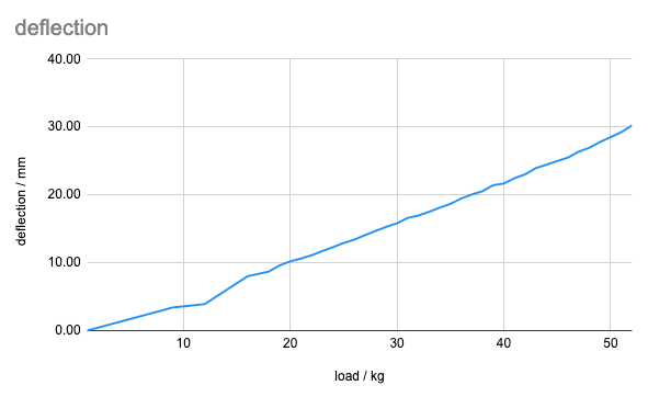
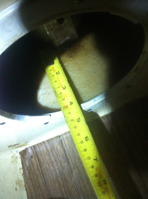
I measured the stick dimensions using the micrometer, and then Dad and I measured the deflection when we applied forces up to about 50kgf. We did this in steps of 2kgf for the first sample. This produced a nice straight line, validating Hooke’s Law and showing that we weren’t passing the yield stress. It also allowed me to calculate the actual Young’s Modulus for the wood at 11.9GPa, somewhat over the guarantee for C16 timber.

Plot of deflection against force for the plain wood samples
Young’s Modulus for the plain wood samples

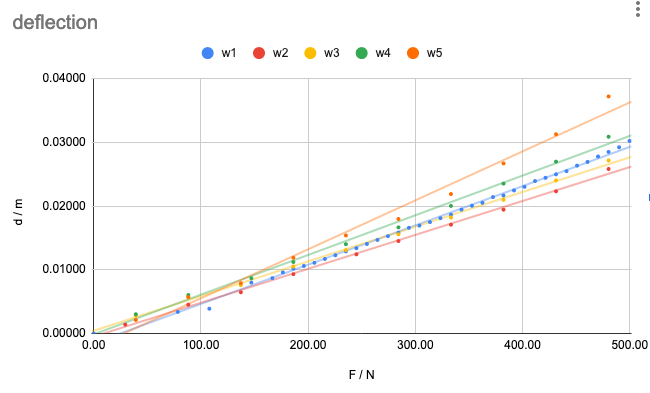
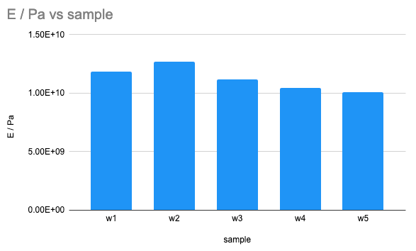
You can look at the measurements, calculations, and results yourself on this Google Sheet. I’ll be updating it as I go.

In the next step, I modified two of the samples by adding a composite to the top surface. I’m using 600g/m² unidirectional glass, and 200g/m2 unidirectional carbon fibre.

IMGA0244

You might be wondering what this unusual unidirectional stuff is. As the name implies, it has almost all of the fibres running along one axis. For the mast in particular, I’m not very concerned with strength around the mast, but with reinforcing it against bending along its length. To do that, I want most of the fibres running up the mast, for the same reason you run the wood grain in that direction.

The Engineering Toolbox gives properties of unidirectional composites. It also quotes the proportion of resin to fibres. So to lay up the glass and carbon I calculated the mass of the fibres and applied, as best I could, the right amount of resin. It turned out that I needed to mix up about 4g more per sample, though. I noticed that the wood took up a couple of grams, and some amount was lost over the edges and in the mixing cup. I’m working with quite small quantities, so I didn’t expect this to be very accurate.

IMGA0246

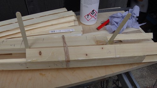
I laid up the fibre by first wetting the wood with epoxy, then laying over the fibre, pouring an even bead of epoxy along its middle, and using my squeegee to spread it evenly and push it in to the fibre. I tried to make only two or three passes to avoid overworking the epoxy and introducing bubbles. But I’m not making these samples too carefully. I’m trying to test what might happen to a real mast, whose surface area is about 2.5m², and so I want to apply a realistic amount of attention.

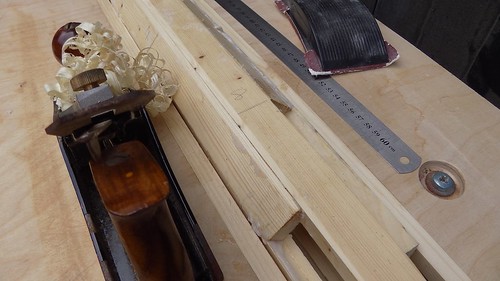
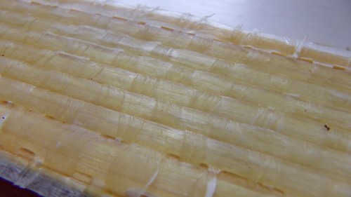
The results after curing aren’t too bad. Here’s the glass, which has come out very neatly. It’s about 0.9mm thick by the micrometer, but the surface is uneven so that’s not all composite.

IMGA0247

The carbon seems harder to keep straight. The tape itself is not perfectly flat before layup, and it’s possible that the slight shrinkage in the epoxy during curing has some effect. I’ve never laid up carbon fibre before so there may be some trick I’m missing. On the other hand, slight waviness in the fibres might help to make the result more elastic and less brittle. I must do some more research on carbon layup. This is about 0.5mm thick by the micrometer.

IMGA0248

Unfortunately, that’s it for now. Storm Alex has stopped all outdoor work for the moment. And it’s probably a good idea to let the epoxy cure for a few days before stressing it.

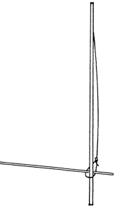
I can say a little bit about how I might make the mast if this works out well. Let’s suppose that most of the mast’s strength comes from 0.5mm of carbon on its surface. That makes it very vulnerable. A slash with a knife at deck level could bring the whole thing down! Clearly, the fibres need protecting, and it has to be possible to know when there’s been damage.

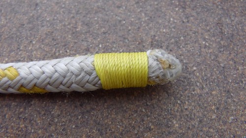
I will need to wrap the mast in another layer of some sort. That layer must be more elastic than the composite, otherwise it’ll end up taking the strain. It needs to be tough to resist damage. But also, it needs to show that damage. My current thought is to use another layer of fibre running around the mast (increasing elasticity), and to use epoxy pigments to dye the layers in contrasting colours so that wear is obvious to the eye from deck level. But it might be that some sort of elastic protective paint would do the job.

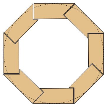
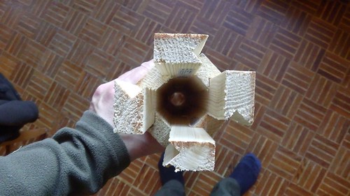
But this does make me wonder whether the fibres can be buried deeper somehow. I found this rather mysterious video of a birdsmouth wooden mast being assembled with some sort of embedded carbon rods.

I am of course not the first person to think of these things. I found this post from Eric Spoonberg in 2004 discussing issues with laying up carbon over wood. He refers to his web site, which is gone, but thank goodness for the Internet Archive, which has preserved this page of interesting free-standing mast projects using composites.

I can also make some predictions of the results. Firstly, there is the Rule of Mixtures, which gives some rather vague bounds using the volumes of the materials. But there is another method using the fact that the materials must all be under the same strain, because they are glued together. In fact, that’s one of reasons that composites work at all.

I’ll come back to this in another post, especially if it keeps raining.

3 Comments

Filed under mast, Repairs and Modifications

So how about a composite mast?

I’ve written about why I need to replace my mast, about wooden mast construction, and in my last article, about how a wooden mast with the same diameter as Tammy’s parners won’t work. Since then I’ve had more than one private message guessing my next move: a composite mast based on a wood core.

As I mentioned in the previous article, the tensile strength of the aluminium alloy in the original mast is probably about 250MPa and it’s in a tube with 3mm thick walls. Basic construction timber has a safe strength of about 10MPa and would need to be 76mm thick to match its strength — bigger than the 50mm available.

Before doing any of these calculations, I was thinking about how I’d coat my wooden mast in epoxy to protect the wood. Then I thought it might be a good idea to sheath it in glass and epoxy for further protection. But, since stresses on are concentrated on the skin, the glass would actually be taking a lot of stress. This is why cored composites work. This video has a nice demonstration of how cored materials behave.

So how about sheathing the mast in layers of glass to achieve the strength while keeping the diameter small?

Once again we can take a look at the Engineering Toolbox to get some starting figures. The tensile strength quoted for unidirectional epoxy fibreglass is 870MPa, however that’s using special S-glass, which has a 40% higher tensile strength than the usual E-glass, so let’s call it 620MPa. That’s still 2.5 times as strong as the aluminium. Furthermore, unidirectional glass mat from East Coast Fibreglass Supplies is made from Jushi E6 320 glass thread, and they quote an experimental tensile strength of 2527MPa in polyester resin, about 10 times the strength of the aluminium!

To be fair, we are not comparing like with like, since the aluminium strength is (I believe) a guarantee whereas the Jushi figures are from testing, but it seems very promising.

Let’s imagine we made a 100mm diameter mast out out of epoxy glass. How thick would it need to be to match the aluminium? (Note: this Python session continues from the previous article.)

seg = 620e6
Ieg = My * y / seg
4.1834724553925743e-07
dieg = (do**4 - (Ieg * 64 / pi)) ** 0.25
0.0977976843453261
teg = (do - dieg) / 2
0.0011011578273369543

That’s just 1.1mm, achievable with a few layers of glass cloth.

Perhaps even more exciting, Engineering Toolbox gives a tensile strength for unidirectional carbon epoxy as 1730MPa. Let’s see how that works out.

sc = 1730e6
Ic = My * y / sc
1.4992791458632348e-07
dic = (do**4 - (Ic * 64 / pi)) ** 0.25
0.09922751849306641
tc = (do - dic) / 2
0.00038624075346679887

A mere 0.4mm. There are, of course, problems.

This is all very well for tensile stress on the upwind side of the mast, but what happens to the equally large compressive stress on the downwind side? Can a 0.4mm layer of carbon take it? How about a 0.4mm layer of carbon that’s stuck to wood? So far, I have not found any satisfactory information for how this will behave.

So it’s time for some empirical testing!

IMGA0233

Here’s my three-point test rig. I have some sticks of softwood. The red object is a car crane capable of exerting half a tonne of force. The stick underneath the legs is being bent upwards by the crane through a 100kg spring balance to measure the force. The metal tube provides a fulcrum. The clamped stick is a reference that I use to measure the deflection, using the micrometer (on the pad).

So far I’ve just done a reference run with one stick, measuring the deflection at 1kgf intervals from about 10kgf to 52kgf. I’m pleased to say the results are very boring.

My plan is to repeat this for each test stick, both ways round. I’ll then laminate one side of a stick with glass in epoxy, and another with carbon fibre in epoxy. Then we’ll test those sticks again (both ways round) and see how much stiffer they’ve become.

I also plan to test some sticks to their yield point, and to destruction, to see how much force that takes. And afterwards it should be quite interesting to see how they failed.

And we can of course calculate the actual Young’s Modulus, yield, and tensile strengths of some of the materials and combinations. This doesn’t mean that every piece of composite will have the same properties, but it should give a good indication.

Watch this space.

Bonus video: Selden winding a carbon mast. At one point there’s a screen showing some useful data.

6 Comments

Filed under mast, Repairs and Modifications

Would wood work?

I don’t trust Tammy Norie’s original mast for offshore sailing. I’ve thought about how I might build a replacement using a wooden birdsmouth construction. But how do I know if my replacement is any more trustworthy? That’s the topic of this article.

Warning: this post contains numbers. Many of them wrong.

I must stress(!) at this point that I am not a professional or experienced engineer of masts, nor a naval architect. This article is about what I have done to try to assess the feasibility of a replacement wooden mast. One of the reasons I’m writing it is that I hope to get feedback where I’m wrong or have missed something. Do not use this article as a guide.

The calculations in this post are written in Python. This makes them easy for anyone to repeat.

Tammy Norie’s existing mast is 8m long, of which about 1.25m is buried beneath the deck. To use terminology from Practical Junk Rig, the Length Above Partners (LAP) is about 6.75m.

L = 6.75

It’s made from a heavily modified aluminium tube with a diameter of 4″ (we’ll call that 100mm) and a wall thickness of 3mm.

do = 100e-3
t = 3e-3
di = do - 2 * t
0.094

For the sake of this discussion, I’m ignoring the part of the mast below the partners, and assuming that the mast is a cantilever beam anchored at the deck. I’m also assuming that the force on the mast is evenly distributed along its length, because that’s a reasonable approximation of the pressure from a sail.

Here’s a diagram of what’s going on in the mast when the boat is heeling.

The wind pressure pushes on the mast. Internal stress within the mast converts this into a twisting moment at the partners, giving a sideways force at the partners and the step that pushes the boat over. What stops the boat from immediatelly falling over is the righting moment — a force that comes from a combination of buoyancy and ballast.

We can draw a similar diagram for when the boat is running before the wind. In that case, the bow of the boat is pushed down and the stern raised. The upshot is much the same though.

There are of course more possible forces than this, especially if the boat is oscillating, or has been knocked down and has its mast in the water. But here I am working towards some basis for comparison between masts, as you’ll see.

I believe we can use all the standard engineering formulae that apply to a cantilever beam, such as those provided by the excellent Engineering Toolbox. (And of course these match the fomulae I find in my dad’s engineering books first published by the Victorians!)

Here’s a useful diagram from Engineering Toolbox. In this case, L is the LAP, A is the partners, and B is the mast head. q is the wind force per unit length.

Now we can do some calculations. Suppose there is a wind force on the sail of 1000N, approximately 100kgf.

w = 1000
q = w / L
148.14814814814815

How much should Tammy’s mast bend? First we need to get E, the Young’s Modulus, and I, the moment of inertia. Engineering Toolbox gives us a Young’s Modulus for 6062T6 aluminium alloy of 68.9GPa. I’m assuming 6062T6 because it’s commonly used for masts, but I can’t be sure that’s what Tammy Norie’s original mast is made of.

E = 68.9e9

We can also calculate the moment of inertia for a hollow tube like this:

from math import pi
I = pi * (do**4 - di**4) / 64
1.076246025868629e-06

Now we can calculate the deflection

d = q * L**4 / (8 * E * I)
0.5184305059991821

giving just under 52cm. From my observations of Tammy Norie’s mast, this seems about right. This gives us some confidence that we’re on the right track. We also want any replacement mast to deflect by a similar amount, and that will help us decide the material and the diameter.

But how strong is Tammy’s mast? Well, the maximum stress on the mast happens at the partners. In fact, it happens at the outside skin of the mast at the partners. (And this is why we don’t want holes near there.) We can calculate the stress from the moment at the partners, M, and the radius of the mast.

y = do / 2
0.05
M = q * L**2 / 2
3375.0
s = y * M / I
156795004.06405988

That gives a stress of 157MPa for our example force on the mast. But we can rearrange this formula to get a maximum force instead.

When a material like aluminium is stressed, it stretches (or compresses), but when the stress is removed it returns to how it was, as long as the stress is less than the yield stress. Of course, we do not want our mast to permamently bend (or break). We can look up the yield stress of 6062T6 aluminium alloy as 241MPa.

sy = 241e6
My = sy * I / y
5187.5058446867915
qy = My * 2 / L**2
227.70944722904983
wy = qy * L
1537.0387687960863

That gives a moment that could cause the mast to bend permanently, My, of 5188Nm, and a wind force, wy, of 1540N, or about 154kgf. That doesn’t seem like an awful lot! That’s about the weight of one human standing on the end of the mast if the boat were on her side.

I do not know the correct righting moment for Tammy Norie, but Selden’s righting moment calculator gives an estimate of 4100Nm. That seems a little tight, but it does mean the wind shouldn’t be able to bend the mast before knocking Tammy over sideways, though it might well be able to dismast me on a run.

As an aside, I’ve sailed Tammy downwind under full sail in a force 7 wind. That’s about a 16m/s wind, which we can plug in to a wind force formula using her sail area of 18.3m², assuming a flat-plate drag coefficient of 2.0.

v = 16
SA = 18.3
P = 0.613 * v**2
156.928
f = SA * P * 2.0
5743.5648

This suggests that Tammy Norie’s actual mast has been under a wind force of 5740N, nearly four times the safe yield limit for the aluminium.

Now, what if we want to build a birdmouth wooden mast, as I described in my previous post in this series? We should be able to use these calculations to work out if we can make a mast that’s at least as strong as Tammy’s 3mm aluminium tube.

It’s a bit tricky to get engineering figures for wood. There are standards for construction timber, such BS EN 388 which specifies certain properties. For example, it says that C16 timber has a safe tension load of 10MPa and a safe compresive load of 17MPa.

What if we used the safe figures promised by BS EN 388? What if we built the mast out of really cheap C16 construction timber? It needs to withstand the same moment, My, as the aluminium mast.

sc16 = 10e6
Ic16 = My * y / sc16
2.5937529223433962e-05
dic16 = (do**4 - (Ic16 * 64 / pi)) ** 0.25
ValueError: negative number cannot be raised to a fractional power

What does this mean? Well, there is no inside diameter that works. Even a solid C16 mast wouldn’t guarantee to be as strong as the aluminium tube. Boo! In fact, we can calculate the minimum stress requirement for a solid mast to match the aluminium.

Isolid = pi * (do**4 - 0) / 64
4.9087385212340526e
ssolid = y * My / Isolid
52839500.640000045

This gives a minimum yield strength of 52.8MPa, and there is no wood class that guarantees this. Tammy Norie’s 100mm mast is just too slim!

So what would the outside diameter of a C16 wood mast need to be?

doc16 = (Ic16 * 64 / pi) ** 0.25
0.15161412929775825

That gives an outside diameter of 152mm. As it happens, the inside of a cylinder doesn’t really do all that much, because the stress is concentrated at the surface. So we can calculate that if the wood were 50mm thick, the diameter would still only need to be 153mm as that still gives a stress under 10MPa.

I50 = pi * (0.153**4 - 0.053**4) / 64
2.651164514924116e-05
s50 = y * My / I50
9783447.64250753

For comparison, in Practical Junk Rig, Haslar and McLeod give a formula for calculating the diameter of a wooden mast with thickness that is 20% of the diameter. They don’t give a derivation of this, but here’s how it works out, based on Tammy Norie’s sail area of 18.3m².

SA = 18.3
doPJR = (L + 2 * SA**0.5) / 85
0.18006705711156443

So that gives an outside diameter of 180mm and a thickness of 36mm. That seems chunky even for cheap wood! We can plug this result into our engineering formulae to calculate the stress such a mast would create.

diPJR = doPJR - 2 * (doPJR * 20/100)
0.10804023426693865
IPJR = pi * (doPJR**4 - diPJR**4)/64
4.49185623973911e-05
sPJR = y * My / IPJR
5774345.3572638

So PJR’s mast would stress its material by only 5.77MPa when under circumstances that would cause the aluminium mast to yield. Quite a safety margin.

Arne Kverneland, a well known junk rig builder, says in his chapter on wooden masts, that PJR’s formula

… has proven to be very conservative unless you rig with a SA/disp. of around 14. More often than not, it will result in over-strong and heavy masts. … On a little boat, any SA/disp. below 20 is for chicken.

He calculates a mast diameter from the displacement of the boat, reasoning that the sail can always be reefed. Indeed, that’s one of the great advantages of the junk rig, and I too, am planning an increase in sail area. Tammy Norie has a notional displacement of 908kg, and salt water has a density of 1025kg/m³, so we can work from there.

m = 908
SAAK = 14 * (m / 1025.0) ** (2.0/3.0)
12.913263838140487
doAK = (L + 2 * SAAK**0.5) / 85
0.16396477655941352

So Arne’s formula suggests an outside diameter of 164mm. Let’s work out what stress that causes.

diAK = doAK - 2 * (doAK * 20/100)
0.09837886593564811
IAK = pi * (doAK**4 - diAK**4) / 64
3.0880976663585186e-05
sAK = y * My / IAK
8399193.298189778

So Arne’s mast would cause a stress of 8.40MPa at the yield moment of the aluminium mast — a reasonable margin under what is promised by our cheap C16 timber.

Of course, that’s still way below what the timber will actually bear in practice. To illustrate this point, let’s look at an average tensile strength for wood. The US Department of Agriculture publishes a very extensive list of properties in “Wood as an Engineering Material”, but even it says

Relatively few data are available on the tensile strength of various species of clear wood parallel to grain.

But it does have a few sample figures in its table 5-7, “Average parallel-to-grain tensile strength of some wood species.” Sitka spruce is often used to build boat spars, and it gives an average tensile strength as 59.3MPa.

sw = 59.3e6
Iw = My * y / sw
4.373950965165929e-06
diw = (do**4 - (Iw * 64 / pi)) ** 0.25
0.057451695315429104

So even with a 100mm mast, this gives an inside, diw, of 57.5mm, or a wood thickness of 21mm. I will repeat that this is based on average breaking stress figures for the wood, compared with minimum yield stress figures for the aluminium, so I wouldn’t trust this.

So, what is the conclusion from all this?

A trustworthy offshore purely wooden mast for Tammy Norie is feasible, but probably only if I increase the diameter of my partners. That’s not terrible, since Tammy has quite a large 150mm aperture at the level of the partners beneath the mast cone.

IMGA0199

Still, I’d rather not start cutting.

So what about an impurely wooden mast? This will be the topic of my next article.

IMGA0219

19 Comments

Filed under mast, Repairs and Modifications

Ascending bird experiments

Tammy Norie’s original mast has suffered some damage, and has a number of possible weaknesses (a hinge, holes) that make me reluctant to trust it for sailing offshore. So I started thinking about how I might build a replacement.

Since I don’t have the facilities at home to extrude aluminium or forge steel, the obvious choice is wood, though as you will see later in this series, composites such as fibreglass or carbon/exoxy are not out of the question.

There are a number of ways to construct a mast out of wood. Quite a few are covered by Haslar and McLeod in the excellent Practical Junk Rig, chapter 8. The most obvious is to find a piece of mast-shaped wood from a single tree! Aside from the difficulty in sourcing a mast this way, there are all sorts of problems with knowing that your mast is strong and reliable; it’s hard to inspect the inside of a tree trunk. The mast would also be solid and heavy.

By building a mast from smaller pieces of wood, we can form a kind of composite. The smaller pieces can be inspected and tested. Imperfections and flaws can be distributed randomly, reducing their impact. And the grain of the wood can be turned in different directions, reducing the chance of fracture or warping.

There are quite a few possible ways of doing it. I recommend a look over the article “Wooden Mast and Spar Building”, which has useful diagrams.

The method looks best to me is the modified birdsmouth, and in particular the octagonal version, where 45º cuts are made along the edge of planks to allow them to join together in an octagon. The outside of the octagon can then be smoothed into a circle — important for distributing chafe and load.

Modified octagonal birdmouth section

I decided to try this out. These cuts would be tricky to make by hand, so I ordered a birdsmouth router bit. Not having a suitable router, I jury rigged one using my dad’s pillar drill and a temporary fence.

IMGA0965

I used this to make birdsmouth cuts along the edges of some cheap 34mm × 18mm softwood.

IMGA0967

Altogether I made 16 staves so that I could try out jointing ideas. An important thing here is that I deliberately did not make them accurately. In my mind, I could see that the birdsmouth arrangement should compensate quite well for defects and inaccuracies, and I wanted to test my theory. It’s very useful to have a forgiving construction technique, especially when you’re an amateur woodworker.

The pieces are really nice to handle, and very easy to assemble. With just a little pressure the octagon holds together very firmly with no play. An elastic band is plenty to keep a model together for experiments.

IMGA0089
IMGA0969

There are several videos showing birdsmouth spar construction. One I particularly recommend is “A Whisker Pole for Julia”.

If you watch that video or read more about this method of construction, you’ll notice that it requires the staves to be as long as the finished spar. In some cases that means buying long planks, and in others the builder scarfs together planks in order to create long staves. This makes sense, but it creates a few difficulties:

This is where my real experimentation starts. I wonder whether it’s possible to create an indefinitely long spar in sections. I had sat around imagining various schemes, and now I had the parts to try out a few.

The basic plan was to assemble one section (a set of eight staves) in such a way that another section could either be joined to it, or assembled on its end. This process could then be repeated to create a long spar. This would naturally limit the amount of surface that needed gluing, end each section could be aligned and glue allowed to cure before the next is added. This reduces the complexity of assembly, the cost of the wood, and the urgency of the assembly process. (This last one is particulary important if you have ME/CFS and might collapse at any moment.)

Clearly, if you just create two sections with flat ends and attempt to butt them together you’re going to fail. You’re entirely relying on the glue, and a mast comes under a lot of bending force and all that stress will be concentrated on that glue. Fortunately, the fact that we have eight independent staves lets us stagger the joints.

So, what if we crenelate the staves, so that alternate staves interlock with the next section? Here’s a picture of that.

IMGA0968

I tried this. It’s very nice for construction, but it is remarkably weak. Using elastic bands to hold the octagons together is a way to simulate weakness in the glue or wood. This crenelated joint still has four aligned butt joints, and is far too wobbly and weak. I was able to break it apart with a mild bending force using my hands.

One of my other thoughts was to use a helix, rather like a spiral staircase. Why not just glue the staves on one at a time in a helix, building a stairway from the deck to the mast head? It’s an appealing notion, but it doesn’t work at all well. You end up constructing what is essentially a spiral fracture in the mast, making it very easy to unravel with a bit of torque. I don’t have a photo of this because it’s actually quite hard to get it to hold together at all!

Then I realized I could arrange to have no two joints in line by combining the crenelation and helix, creating a double helix. This is a bit tricky to visualize. It’s what is going on in this photo.

IMGA0970

It’s a lot simpler to see if I show you a diagram of how the staves would look if unrolled.

Unrolled double-helix arrangement of birdsmouth staves

I tried this method with my staves, and the joint was very stiff indeed. It would not budge at all, either to bending or twisting forces.

In addition, I found that the two sections would naturally align very accurately when squeezed tightly. I have a geometric intuition about why this might be that I find hard to explain, but I’m hopeful that it would be very helpful when assembling a long spar from sections.

All of this was done before my latest ME/CFS relapse, so many months passed before I was able to make progress. In the past few weeks, though, I have done a bit more.

I have slowly been watching the construction of SV Tapatya, a Benford dory similar to Annie Hill’s famous Badger. Tony decided to eschew epoxy for the main construction and use a urethane foaming glue called Collano Semparoc 60. He discusses why in this video from his building series.

Tony has also carried out some experiments with Semparoc and plywood, boiling and soaking to see if he can get it to weaken. I like this kind of thing!

I thought that Semparoc might make a good glue for building a mast, mostly because of the ease of handling. Aside from toxicity problems, epoxy has to be made up in batches. I read one article about birdsmouth construction where about 20 friends were needed to apply the epoxy in time to get the mast together! Well, my section construction method could help with that, but it could also be helped by easy gluing.

I bought a tube of Semparoc to try out, and used it to glue together a section using my prototype staves.

Firstly, I marked off the double helix offsets a bit more carefully.

IMGA0092

Then I parted the joints using two lolly sticks and squirted in the Semparoc straight from the dispenser.

IMGA0093

As Semparoc cures it foams, reacting with the moisutre in the wood, and filling gaps. This is again important so that perfect cutting accuracy is not required.

IMGA0096

Once the glue cured, I planed off the corners of my octagon to make a somewhat irregular decahexagon.

IMGA0098

I think it’s interesting to look at the joints after planing, which slices some of the foam open.

IMGA0099

This does not seem to make the glue weak (it’s a well tested glue) but it could allow moisture to settle, and might need careful sealing. Mind you, so does the rest of the wood.

The result was this rather nice object, which is also strangely cuddly.

IMG_20200909_081459

And here it is with the staves of the second section slotted in place, but not glued. (You’ll need to click through to look at it in detail.)

IMGA0197

That’s as far as I’ve got so far in building anything. There are a few obvious refinements, such as arranging some sort of interlocking on the end of each stave. I don’t think a full 12:1 scarf is necessary, but something simple might be wise.

For further reading, I highly recommend Duckworks‘ article “Birdsmouth… and Other Wooden Masts and Spars” and also all of the other articles on birdsmouth on the Duckworks site.

The most obvious next question is whether a mast made like this is strong enough overall for Tammy Norie! That will be the subject of my next article in this series. But the answer is no. Or maybe. You’ll see…

14 Comments

Filed under mast, Repairs and Modifications

Scratches and holes in the mast

I recently promised that I’d write about my plans for a replacement mast for Tammy Norie. This is quite a big and complicated topic that I’ve been thinking about for a long time, so it’s going to be a series of shorter articles.

This one is about the problems with the existing mast, and why I’m considering making another.

In August 2017 I noticed that my mast had gained a lot of surface damage, as you can see in this photograph. Ironically, this damage was caused by the screws holding in the anti-chafing strips on the mast and battens. You can see more details in my post, “Little jobs roundup, 2017-09”.

IMGA0618

I started a thread on the Junk Rig Association technical forums to ask for advice, and my conclusion was that I should polish these out to avoid mode 1 fractures that could propagate through the whole mast. Stress on a beam (such as a mast) is concentrated on the skin, and the molecular bonds can unzip if they’re given a start.

However, this thread revealed other problems. David Tyler, a former engineer of masts, rightly criticised my drilling of a hole near deck level to secure the mast sleeve, and even comissioned this cartoon for the magazine!

But that wasn’t the end of it: I realised there were at least seven more holes. This one is exactly at deck level.

IMGA0193

And there are six more rivet holes that support this collar, which itself holds up the mast sleeve.

Tammy Norie's mast has too many holes at deck level.

We discussed various of mitigating the problems in the thread, and I may work on them, but this was really the final straw for me. I do not feel I can trust Tammy Norie’s original mast for long distance sailing. Getting dismasted near the coast is one thing, but on a long voyage I need to be more sure of my boat.

Commissioning an expensive new mast isn’t really in the Tammy Norie spirit. Roger Taylor’s lamp post solution could work, but it would involve cutting the boat around, making it impossible to swap back to the old mast for bridge-ducking coastal sailing. Instead, I started thinking about ways that I could build a new mast myself, and that will be the topic of the next article in this series.

3 Comments

Filed under mast, Repairs and Modifications

Tammy’s twenty twenty

It’s been nine months since my last post. ME/CFS has kept me from making a great deal progress on Tammy Norie. That, and the COVID-19 pandemic have kept Tammy out of the sea this year. Most of my plans for this year were scuppered: meeting three other Coromanels, sailing to Brittany, and attending the International Maritime Festival in Brest (sensibly cancelled). Disability also kept me from writing.

In the past month I have improved a great deal, and made quite a bit of progress, and I find I have quite a lot to write about!

  • I built a third tent for Tammy Norie that helped to dry her out thoroughly over the winter.
  • I have scraped and sanded all of Tammy’s bottom back to the bare gelcoat (and through it in some places) in preparation for an osmosis-preventing barrier.
  • I discovered water inside Tammy’s keels, and have been through a quite unusual drying process!
  • I found weaknesses in the seams around Tammy’s keels, and reinforced both keels with quite a bit of new fibreglass.
  • I have made a start on the closed-cell foam insulation and floatation and can show some details.
  • I have built a prototype for a mast replacement, and have detailed plans to build a complete new mast.
  • I am finally enlarging the cockpit drains, reducing the draining time from around 40 to just four minutes.

I hope to write posts about all these topics, with many pictures and details, in the coming days. Watch this space.

4 Comments

Filed under antifouling, cockpit drains, hull, keels, mast, Repairs and Modifications

Mast screw mystery solved

When I built a new mast step in 2017 I removed the original mast bracket screws, only to discover that they weren’t wood screws at all, but machine screws:

I took a good look down through the holes in the wood and noticed two things. Firstly, the wooden block holding the mast step did not extend all the way down to the bilge as I had expected. There was some sort of void beneath it. Second, there may have been some metal on the other side. Perhaps there was a tapped plate or some captured nuts on the other side. It was very hard to see.

I have solved both mysteries in quite a simple way — by looking in to the bilge with my camera.

Here’s a view forward along the main bilge from the hatch just below the companionway.  You can’t get your eye down here, but my camera was able, and with a bit of fiddling with the settings and flash I was able to get a reasonably clear picture.

IMGA0835

I noticed the strange objects in the distance.  The brown one isn’t that strange: it’s a leaf. But the metalic thing? I managed somehow to get my camera to zoom right in and get a steady-enough shot to reveal it.

IMGA0845

It’s a metal backing plate!  This is no doubt what the machine screw connected to from above.  I expect the reason it is hanging off is that I had to remove the machine screws using an impact driver.  So on the one hand, Newbridge’s engineering wasn’t all bad — they weren’t relying on a machine screw to hold in wood — but it’s pretty bad because there’s absolutely no way for me to get to that plate.

What this also shows is that the mast step block is not resting on the bottom of the boat.  Here’s a picture of it from above, taken through a locker lid.

IMGA0752

Theoretically, I could get this out.  I’d have to cut carefully through the fibreglass tabbing then manoeuvre it out of the triangular locker forward of the mast. My moister meter shows parts of it as being saturated, and this may become necessary at some point. At least now I know what’s going on down there.

5 Comments

Filed under bilge, mast, step

A new mast step

Last week I wrote about my plan to rebuild my mast step. The job is mostly done, and Tammy Norie has a sporty new rake to her mast. This article will describe how I did it, including mistakes and remedies.

If you want to know about the design and thought behind it, you should read my post “Raking the Mast”.

Here are the materials I bought for this job:

  • 50mm × 50mm × 6mm × 1m aluminium angle
  • a sheet of 15mm hard rubber block
  • M6 stainless steel studding, 2 washers, 2 nuts
  • 8 × M8 coach screws and spring washers

The total cost is around £40.

The biggest modification to the boat I needed to make was to cut a larger hole in the berth above the mast step so that I could adjust the angle of the mast. I imagined this would simply mean extending the circular hole into a longer slot. I started out by measuring the area so that I could draw the new hole on the gelcoat. That was when I discovered the first problem: the original hole was not in the middle of the boat!

The distance from the left side of the hull to the centre of the mast was 535mm, but from the right side it was only 485mm.

IMG_20170918_133852
IMG_20170918_133916

I checked this several times, and looked at the mast from several angles. I adjusted the contents of the boat to get her perfectly level, and took at look at the mast from the dock using my spirit level. The mast was definitely leaning to port by a small amount. Oh Newbridge! Well, I suppose I could correct that now.

I found and marked the actual centreline from the hull sides, and that allowed me to draw enlarged hole, with enough side-to-side-to-side movement to fix Newbridge’s mistake.

IMGA0658

The next job was to remove the existing mast step bracket. This is a well-known weak point. Mine had been making ominous clonking noises on my crossing of the North Sea in 2015. It’s a known weakness. What’s more, it had been replaced on every other Coromandel I’d seen.

Down with the mast!

IMGA0662

Out with the mast stub!

IMGA0675

This exposed the bracket, held in with the two largest wood screws I’ve ever seen.

IMGA0678

I had been wondering how I would get these out. None of my screwdrivers were big enough, and a sailing friend has said I would need some violence to remove them. Fortunately, I was able to borrow an impact driver from Dad’s workshop; a tool specifically designed to apply violence to screws.

IMGA0686

This tool applies a turning force when you hit it with a hammer, making it ideal for freeing up screws that have been in place for 35 years. It worked very well indeed. Out came the screws and the bracket.

IMGA0687

The observant among you may have noticed that these are not wood screws at all. They’re machine screws, designed to fit into nuts or tapped holes. The threads really don’t hold well in wood. Was this more poor engineering from Newbridge, or was there something I’d missed?

I took a good look down through the holes in the wood and noticed two things. Firstly, the wooden block holding the mast step did not extend all the way down to the bilge as I had expected. There was some sort of void beneath it. Second, there may have been some metal on the other side. Perhaps there was a tapped plate or some captured nuts on the other side. It was very hard to see. [Edit: See Mast screw mystery solved.]

Unfortunately, this is yet another area unmaintainable area of the boat.  There’s no way to get to the other side of the wood without tearing the boat apart. I made a note to inspect the area with an endoscope during the winter.

I also checked the moisture content of the wood. It was off the scale on my moisture meter!

IMGA0694

The plywood the mast is standing on is untreated, as far as I can tell, and has been getting quite wet. I made another note to dry this area thoroughly during the winter and think about how I could treat, seal, and reinforce the wood.

Next, I checked the exact dimensions for the new step by standing the mast step in the aluminium angle. The rubber chocks would be 15mm thick, and I planned to have then compress by about 2mm. The mast appears to be a 4″ tube, so that made the interior width of the step box 13mm.

There followed about an hour of hacksaw work in the workshop at the Fareham Sailing and Motorboat Club. I like to work on projects aboard as much as possible, but this really did need a good bench vice.

I’m very glad I chose to build in aluminium rather than stainless steel. I had enough hacksawing of stainless steel to last a lifetime when I built the Hebridean. (These days John Fleming is offering pre-cut kits!) The rubber block was relatively easy to cut with a hacksaw, provided you oiled the blade.

It turns out my beloved tea flask is almost exactly the same size as my mast, so I was able to use it to get a rough idea how things were coming together.

IMG_20170918_210301

The next morning I test fitted the step box around the actual mast.

IMGA0710

And I checked that the mast would be clear of any screw heads one it was standing on a rubber chock.

IMGA0713

Next, I drilled holes for the coach screws and the mast pin. I chose positions for the holes about two thirds of the way out, because the mast forces well be attempting to lever up the angles. I also chose too align the holes in the end angles with those in the sides so that the holes are in a rectangle, just in case.

IMG_20170919_144724

I’ve only made one pair of holes for the mast pin so far, with the mast base as far aft as possible. This is so that I can test the mast with forward rake. If I decide to alter the rake I will make more holes. There’s plenty of room for four positions or more.

IMGA0714

I checked how the mast step box fitted in the boat, but since the coach screws hasn’t arrived the post, that was all for that day.

IMGA0719

The next morning I had my coach screws from Sea Screw. These are rather special: large screws with threads designed for wood but with hexagonal heads that can be turned with a spanner or socket. The next person to undo them won’t be using an impact driver.

IMGA0722

So far, no permanent changed had been made to Tammy Norie. It was time to make cuts. After carefully re-thinking everything, I enlarged the hole in the berth using a coping saw.

IMGA0729

And then I carefully lined up the mast step box, made pilot holes, and screwed it down.

IMGA0739

I’m eliding a lot of difficulties here. As I suspected, access to the wooden block was very difficult. I wasn’t able to use my battery drill to make pilot holes, and had to fish out my poor-quality hand drill. It was slow going and the pilot holes were not perfectly straight.

You can also see that the box isn’t lying flat on the wood. The wood is partly glassed-over and that makes it uneven.

These difficulties were enough to mean my careful measurements didn’t with out and the mast wouldn’t really fit between the chocks.

IMGA0741

Fortunately, the solution is fairly obvious: make a base for the box separately and then fix the whole thing down.

IMGA0745

Just right! With this change the mast could be pressed firmly down between the chocks, gripped tightly, but with no possibility of abrasion.

IMGA0748

With this done, I disassembled used a punch through the holes I’d made for the mast pin to mark positions for holes in the mast. These were a bit closer to the mast end than I’d like, and for this reason I’d recommend making a taller box of you’re planning to do something similar — 100mm tall I suggest.

I then drilled 6mm holes in the mast for the pin, and tried to put everything back together. For about an hour.

The thing is, it’s very difficult to navigate a piece of threaded stainless steel studding through six not-quite-lined-up holes when two of them are made of rubber and all of them are in an awkward place you can barely see.

After a while I disassembled the whole thing again and enlarged the holes in the rubber using a 10mm drill bit. The holes still ended up much smaller than 10mm, but at least the studding went through them without force. I also enlarged the holes in the mast to 8.5mm so that I had a hope of finding them.

It still to another 30 minutes of fiddling to get the pin through, and I was very relieved when it popped out of the other side of the box. After that I was very reluctant to disassemble the step again!

I think this could be made much easier by fitting a tube through the mast to guide the pin. I may do this later. I certainly recommend it to anyone making a step like mine.

You might notice that there are no chocks fore and aft of the mast. I’ll be making these soon. In order to maximise the forward rake of the mast I did not leave enough clearance for a 15mm chock. I’ve ordered thinner rubber for this job. I believe the step is already significantly stronger than the Newbridge bracket, and I can make tests of the mast position without these chocks. But for the long term I wasn’t to make sure that the pin isn’t taking any load.

Fortunately, I found that I was able to re-arrange my existing mast partner wedges to fit around the mast in its new position. They aren’t a great fit, and I plan to make more, but for testing these are good enough.

IMGA0750

The next snag was that the disc that helps keep the wedges in place no longer fitted over it’s bolts!

IMGA0753

This was a fairly obvious mistake on my part. The new mast angle has shifted this disc back slightly.

The remember this disc puzzling me when I first got Tammy Norie. It’s made of heavy gauge stainless steel and is probably one of the strongest items on the boat, and yet it’s only job is to keep the wedges from falling out. No other Coromandel owner has such a heavy one, so I suspect this is a modification by the original owners.

Fortunately, there was some ideal scrap plywood in the workshop — the seat of some school chairs. This wood had been moulded for sitting on, and so had a nice circular depression in the middle. Turned upside-down that depression will press upwards against the wedges.

Rather than make a complete disc I decided to make two half-discs with an overlap. And instead of bolt holes I would make slots. This would make the new disc capable of being added or removed without removing the mast, and able to cope with mast rake changes.

I marked up the wood.

Then I put the coping saw to use again.

IMG_20170922_113727

Checked the positions of the bolts.

IMGA0777

Cut slots and then smoothed everything in to shape with my surform.

IMGA0779

Not bad!

Finally, I was able to put the interior back together and make Tammy more like home again.

IMGA0781

There are still a few problems to solve, as you can see here.

IMGA0782

Finally, here’s the best picture I have showing the new mast rake. I think it looks rather interesting and attractive.

IMGA0795

So far I have not had a chance to test the new sailing characteristics. Soon, I hope.

There are more pictures with descriptions in this Flickr album, showing the steps in more detail.

14 Comments

Filed under A New Rig, 2017-2018, mast

Little jobs roundup, 2017-09

Here’s a roundup of small jobs done on Tammy Norie in late August and early September.

When comparing Tammy Norie and Emmelène, I suggested we drop Tammy’s mast and lift the mast stub. When we went to remove the retaining bolt, it snapped!

https://flic.kr/p/WTVrFA

IMGA0194

I cut a new bolt from stainless steel studding.

IMGA0673

I suspect the wear on the bolt was the main cause of the clonking sound that’s been gradually building up when Tammy is in rough water. This also gave us a good chance to look at the rather inadequate mast foot bracket.

IMGA0198

This is due for an upgrade later when I improve the mast step.

My engine starter cord snapped at an inconvenient moment on the way in to Portsmouth Harbor. I’d only just replaced it. This time I noticed that the cord was slightly melted. Moral: don’t use melty synthetic string for your engine starter. Use cord specifically designed for the job.

Replaced the incandescent bulb in my trusty utility lamp with a domestic halogen-replacement LED that I just happened to have knocking around. Half the power and a great deal brighter — possibly too bright.

IMGA0544

Replaced the coaxial connectors on my log and depth instrument. They were being to corrode and the log was unreliable. I had to dismantle the instrument and desolder the old connectors from the circuit board. I bought a pack of 10 replacement connectors from eBay so that should keep me going. NASA Marine were very helpful.

I am finding my new Iroda SolderPro 70 butane soldering iron very useful.

While I was doing that I fixed another problem with the instrument: it’s too bright at night. I couldn’t find a way to do this electronically, but I discovered that the backlight and the display are physically separate. I cut a piece of paper to slip between them and the display is much less dazzling.

IMGA0545

The charts in my Solent chart pack were getting dog-eared, so I’ve edged them all with Scotch Magic tape, which is nearly invisible and takes pencil marks.

IMGA0601

The bow light hack finally failed after two years. The LED replacement bulb fell apart somewhere inside so that the terminals no longer connect. This is probably because it was not designed to be shaken about on the bow of a small boat. I ordered a couple of made-for-purpose replacements, one of which is now in the bow. The other is a spare for either bow or stern.

My mast lift is now a spare halyard. The mast lift is a loop holds the forward part of the sail bundle when the sail is reefed or lowered. Practical Junk Rig (fig. 3.49) has it as a single line from the mast head.

wp-image-1355314572

Practical Junk Rig figure 3.49

I’ve repurposed the enormously long “burgee halyard” that came with Tammy as a spare halyard in it’s place. I’ve felt the need ever since my halyard came off in the Waddenzee. Thanks to Chris Edwards for this idea. (The arrangement below is temporary until I make a new soft shackle.)

IMGA0622

I may re-rig it a shown in Practical Junk Rig figure 3.50b, using the spare halyard on one side, allowing me to reef upwards!

wp-image-1478996357

Practical Junk Rig figure 3.50b

I found and installed a pair of calibrated quick links for the series drogue. It’s surprisingly hard to find shackles that are rated for load, but these beauties are good for at least 12500N each, more than the weight of the boat, and more than the greatest expected load on the drogue. (The drogue still doesn’t exist, in case you’re looking for it.)

I whipped some rope ends!

IMGA0721

I rewired my switch panel using some new terminal blocks and rules: each piece of equipment goes to its own terminal, then switches are wired to terminals using colour-coded jumpers. Much neater, and a model for how I’ll do things when I remake the panel.

IMG_20170922_172631

Expect more small jobs next month.

1 Comment

Filed under electrics, engine, instruments, lights, mast, Repairs and Modifications, rigging

Raking the mast

The idea of raking Tammy Norie’s mast forward first came up when I compared Tammy to Fantail several years ago. As far as I can make out, raking Tammy’s mast will have three advantages:

  1. It will help the sail stay out in very light winds — particularly useful when becalmed.
  2. It will cause me to rebuild Tammy’s mast step, which is a known weak point.
  3. It will shift the centre of effort of the sail forward, improving the balance of the boat and reducing weather helm.

I believe I can achieve about 5° forward rake by moving the mast step aft, pivoting the mast within the cone that forms the partners.

IMG_2931
IMG_2932
arctan(10cm/118cm) = 4.8° I believe.

This should being the centre of effort of the sail (shown below) forward by about 3.5m × 10cm/118cm = 30cm.

IMG_2974
Because nobody has done this on a Coromandel and the future sail plan is unclear, I’ve come up with a scheme to make the rake adjustable.

Firstly, here’s s picture of the existing step. I hope you can see why this is inadequate. It’s been replaced on every other Coromandel I’ve seen!

IMGA0198
Here’s a drawing of the mast step that will make raking possible. I’m afraid I’m writing blog articles on my phone recently and so I don’t have my nice diagram software. You will have to make do with a photo of my pencil drawing.

This is basically a rectangular box made of aluminium angle, into which the mast is wedged using hard rubber chocks, and further secured with a retaining pin (to stop the mast wandering or jumping out).

The box is screwed to the laminated wood block that’s already glassed into Tammy’s hull, using large coach screws (hex heads and wood threads).

The mast base can be chocked and pinned at various positions in the box, allowing various angles of rake. Of course this means adjusting the blocks in the mast cone, so it’s not something to do at sea. I tried that (accidentally) once.

To allow for this I need to enlarge the hole in the berth that the mast passes through, making it into a round-ended slot.

IMG_2927
The box could be strengthened in various ways, but I already have 6mm gauge aluminium angle — double the gauge of the mast itself — so it ought to be fine.

Incidentally, the reason that the angle turns inwards is that it’s very hard to get tool access to this area of the boat. I don’t think I will be able to make pilot holes for the coach screws except through the slot for the mast. Having the screws inside also makes them possible to inspect through that same slot.

I hope this will all become a lot clearer when I start doing the work and have some photographs.

In the meantime, is be very interested in criticism or ideas for improvement.

19 Comments

Filed under A New Rig, 2017-2018, mast, Repairs and Modifications