Monthly Archives: June 2014

Wash kit and nose plug test

We finally got hold of a wash kit for Tammy Norie’s engine. A wash kit allows the engine to be flushed through with water from a hose (cleaning out salt) and also allows the engine to be tested out of the water. This gave us an opportunity to test the nose plugs we made earlier that prevent fumes blowing back into the engine compartment and cockpit.

Thanks to Martin at Hendy Honda Marine who helped to identify the engine and found the part in a warehouse in Belgium, as well as putting together a nice spares kit.

Leave a comment

2014-06-30 · 19:53

Lifejacket test

We didn’t know the age or condition of the lifejackets we received with Tammy Norie, so it was time to test them. They passed and were still nicely inflated 24 hours later.

Thanks to Versatile Marine for their servicing video.

Leave a comment

2014-06-30 · 12:09

Boat stamp

Every boat needs a stamp, I think. I just got back from skippering in Sweden and found that Stamps Direct had delivered my order for Tammy Norie. They worked from custom Photoshop artwork I made and have excellent customer service.

IMG_2791

3 Comments

2014-06-30 · 09:58

Mast raising demonstration

Raising the mast and sail now that the hinge has been reinforced.

This is an easy one-person job now, though I have yet to try it in the water. It would be much quicker than shown in the video if I wasn’t fiddling with the sail cover, too.

This video shows an experimental mast gallows made by crossing the oars with a bungie cord. It seems like a good way to keep the mast out of the way while travelling with it down.

30kg force is required to lift the mast when standing on the sliding hatch. I measured this with a 100kg spring balance I found in a hardware shop for £3 — very handy!

Leave a comment

2014-06-21 · 23:42

Early summer plans

The summer sailing plan for Tammy Norie is taking shape.

Firstly, I’m keeping an online calendar of plans that you can subscribe to if you like. The next few upcoming events will also appear on the side of this blog.

Next week I’ll be skippering a sailing trip in the Baltic with the Cambridge University Yacht Club, so Tammy Norie will have to wait in my parents driveway for a little longer.

Though I live in Cambridge I’m hoping to join the Fareham Sailing and Motorboat Club and moor Tammy Norie in Portsmouth Harbour. This is close to my family, offers sheltered sailing for my nephews and niece, and my uncle is already a member. I visited the club and very much liked the people but they don’t hold membership meetings very often and I’m having to be patient. I’m hoping we will sort out membership and mooring by September.

So in the meantime I’m going to explore East Anglia.

The plan is to launch on 4th July at Woodbridge on the beautiful Deben. We’re going to try a launch directly from the road trailer this time, without a crane. It should be an interesting exercise! We’ll probably try a partial retrieval too, just to get an idea of the problems. (I’ll write about my launching trolley ideas later.) The rest of the weekend will be spent exploring the Deben and possibly taking a trip to a neighbouring river. I’m keen to put Tammy Norie through a few more trials.

I have some friends going to the Latitude festival near Blythburgh on 19th-20th July. A bit of research (thanks, Dylan Winter) revealed that I can sail Tammy Norie to Blythburgh from Southwold by ducking the mast under the old railway bridge. So that’s the plan for that weekend. Southwold itself looks like a great place to visit. If conditions are poor I might go to Aldeburgh instead.

The Junk Rig Sailing and Rally Club are holding a rally at Bradwell on the 26th-27th July so I’ll take a long weekend to explore the area as well as meeting a bunch of other junk sailors. I don’t know if Mingming II will still be in England then, but I’d love to take a look at her.

After that I have friends taking a holiday in Sheringham for the week of 4th August. An excellent excuse to sail right around the coast to Blakeney and Wells. By that time I should have a pretty good idea of Tammy Norie’s sailing capabilities so a longer trip should be very feasible.

After that the plans are more vague, but I’m quite keen to bring Tammy Norie home to Cambridge! From Blakeney it’s a short sail round to King’s Lynn and the mouth of the Great Ouse, which joins the Cam south of Ely. It would be quite something to see her in Cambridge and I might even be able to get her and my house in the same photo with careful angles. If I do sail to Cambridge we’ll probably haul her out nearby and trail her to the Solent rather than trundle all the way back.

Screen Shot 2014 06 16 at 10 44 48

This plan is slightly confounded by the separate regulation of inland waterways. To take Tammy Norie to Cambridge I’ll need a boat safety inspection, an Environment Agency licence, and a special licence for the Cam too. These are significantly more expensive because Tammy Norie has quite a big engine for her size at 10hp. It’s almost worth buying a smaller engine just for the savings, and I’m looking in to that.

The alternative plan is to sail from Blakeney to Portsmouth in stages. There’s be plenty to see and do that way as well.

I can’t wait.

5 Comments

Filed under East Anglia 2014, Plans

Tammy Norie in print

The Junk Rig Association are serialising this blog in their members magazine, starting at issue 65. Back issues are all available to JRA members for download and it’s a mine of useful information. Recommended.

JRA Magazine issue 65 portrait  best 210MB  dragged

Leave a comment

Filed under Uncategorized

Boat dentistry

I wrote earlier about how I managed to break Tammy Norie’s nose by sweating on a line between it and the mast head. We’re not only repairing the damage but making the whole fitting much stronger.

Here’s a picture of the damage, with me pushing upwards on the anchor fitting.

IMG_2427

It took us a little while to understand what was wrong. The deck isn’t secured to the hull at the stem head except by a thin line of sealant. The deck joint has fixings behind the rubbing strake (which you can see at the bottom right) and seems pretty secure in general, but there’s nothing holding the deck down at the nose except general stiffness of the fibreglass.

At this point we could have squirted a load of epoxy into the gap, squashed down the deck, re-sealed the joint, and hoped for the best. But my principle for Tammy Norie is to fix any damage stronger than before. So I planned to replace the machine screws that hold down the anchor fitting with longer ones that go right through into the anchor locker, and through a reinforcing backing plate.

The original machine screws only go through the deck. Here’s a picture of the inside of the anchor locker looking forward. You might just be able to make out some bumps in the fibreglass at the top.

IMG_2602

After bolting down the anchor fitting, Newbridge made a reinforced fibreglass bubble for the anchor locker, glassing over the nuts! This makes the anchor fitting very hard to remove, as the nuts just rotate and you can’t get a spanner onto them without grinding through the anchor locker. This part of the locker is very small and hard to reach. It’s a terrible bit of unmaintainable design.

Dad and I discussed what to do. Even if we drilled out the stainless-steel machine screws (an awful job) the nuts would still be floating around. Since the damage had partially cracked the deck along a line behind the anchor fitting, I thought perhaps we should just cut right through it, remove the section of deck, then attempt to make the whole thing good after bolting it down. That would have been another big job and difficult to get right.

A week or so later I realised that when I’d ripped up the fitting I saw it rise to an angle of about 40 degrees. Given that the alternative was making a cut, I should just try prying it open to see if I could reach the nuts. There wasn’t much to lose. So I rigged up a rope from the fitting and pulled it tight.

Open wide, Tammy Norie!

IMG_2593

What lovely shiny teeth you have!

IMG_2596

The “tongue” you can see is the top of the anchor locker bubble.

We were able to get a spanner onto the nuts and undo the machine screws, removing the fitting. To get the last couple of screws out I used a wedge to keep her mouth open.

IMG_2597

IMG_2598

IMG_2600

With this done we were able to drill the holes through to the anchor locker. I started making a template for a backing plate from cardboard. Dad took over most of the work from here as I was busy making the new mast hinge.

IMG_2709

Here’s the finished template and the aluminium plate he cut.

IMG_2702

IMG_2704

I had a lot of fun drilling the perforations. These are intended to capture resin and fibreglass to increase the strength of the bond between the plate and the hull. At this point I tried to bend the plate in the right place, but it was incredibly hard to get a good fold because of the awkward shape. Dad made a jig from some hardwood, annealed the plate, and did some hammering. The result: one rare specimen of the anchor backing plate moth!

IMG_2712

You have to imagine this turned upside-down and inside the anchor locker, pressed to the ceiling. The machine screws come down through the anchor fitting, the deck, and the ceiling, then through the plate and onto their nuts. We haven’t decided whether it’s worth keeping the hardwood block as well. It’s already a tight fit and it took quite a lot of work to get the plate into position.

Edit: Here’s a photo taken later of the moth in position.

IMG_2757

So far that’s as far as we’ve got. The fitting is bolted down and already more secure than before. We could, at this stage, re-seal the deck joint, seal the machine screws, and call the job done. But that’s not good enough. At the next opportunity we will add a layer of fibreglass over the plate, and especially over the perforated “wings” so that the anchor fitting is connected firmly to the hull as well as the deck. It should then be able to take a reasonable amount of upward load, allowing us to experiment with headsails without worry.

I’ll post pictures when the job is done.

For comparison, here’s a modification made by Declan McKinney for Galway Girl. He didn’t suffer damage like I did, but writes:

I must say I was nervous about the deck lifting just from the boat bouncing on its mooring, hence the upgrade.

Declan has gone for an external reinforcement with his anchor fitting on top. You can find more details, including a CAD drawing, at the Corribee & Coromandel Discussion Group on Yahoo.

Bow+fitting

1 Comment

Filed under anchor-fitting, Repairs and Modifications

Making the mast hinge: blood, sweat, and Duralac

I made the mast hinge improvement this past weekend and it was a complete success!

Firstly, we paid a surprise visit to MG Metals who had a very fine piece of aluminium alloy bar. I think they were a bit puzzled by me and Dad just turning up, but were very helpful and sorted us out in five minutes. It wasn’t so easy to buy stainless-steel machine screws. Screwfix seem to have given up selling screws. Fortunately, B&Q had a few. We ended up with 5mm pan-head screws and a few countersunk screws for fixing through the hinge outer.

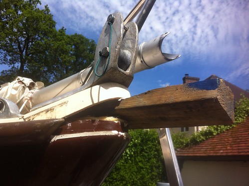
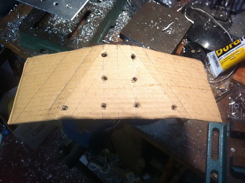
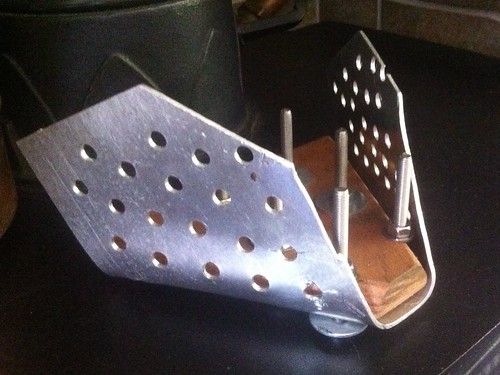
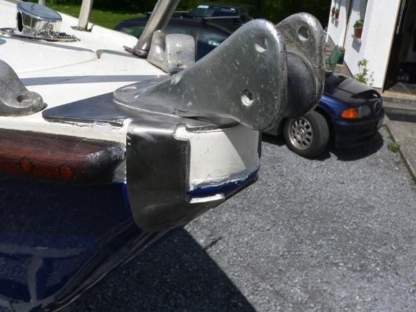
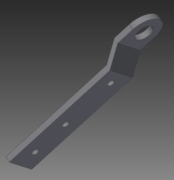
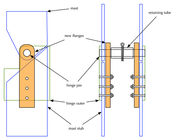
The first step was to work out an appropriate length for the flanges. We settled on 200mm. Dad suggested we put as six screws through the mast in each flange, and stagger them for strength. I cut a single 200mm flange and we drilled a centred 12mm hole at the top for fitting. Here it is hanging into the mast stub on the hinge pin I’d already had made, with the mast folded down and resting on the back of the boat.

IMG_2605

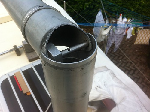
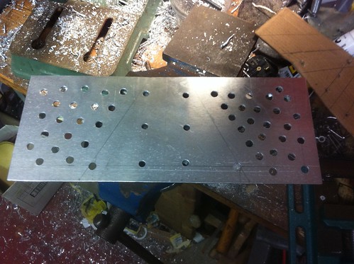
I found positions for the six screws and drilled 5mm holes in the flange. Then came the nerve-wracking stage of drilling holes in the mast. A committing move. I did this by hanging the flange from the pin on the outside of the mast, aligning it carefully, then duct-taping it into position. I was then able to drill through the screw holes and through the mast. After that, I put the screws through and nuts on the back to test the fit. It took a bit of wiggling and everything was very tight, but I was able to get the pin into position. Here’s the result. 

IMG_2612

At this point I made a second flange, using the first as a template, and repeated the procedure. I also made some thin spacers from plywood so that the flanges didn’t press directly onto the mast. I shaped these with a surform so that their curve fits the mast pretty well, with a flat face against the flange. This gives the flanges a tiny bit of movement but will avoid their edges cutting into the mast when the whole thing flexes. The movement helps with aligning the hinge pin.

IMG_2616

This all took up most of Friday, but we were able to raise the mast on Saturday morning in time for my brother’s family to visit. We did this with guy ropes either side, but it already felt pretty steady, and there was no way that the pin was going to escape.

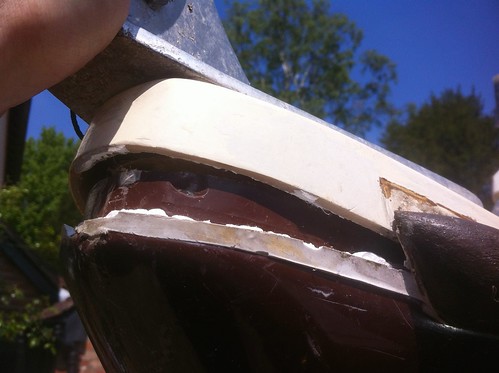
However, we were unable to drop the tight-fitting mast sleeve over the hinge. My screws had spread the hinge outer a little, and it was already an almost perfect fit. We cured this by drilling the holes for the top four screws to 5.5mm, allowing the hinge outer back to its original position.

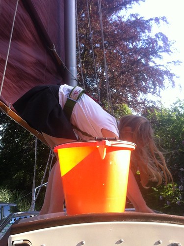
My niece was particularly keen on the boat and set to work scrubbing the decks, though I think mostly she liked throwing water around and playing with the pumps.

IMG_2625

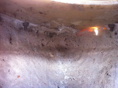
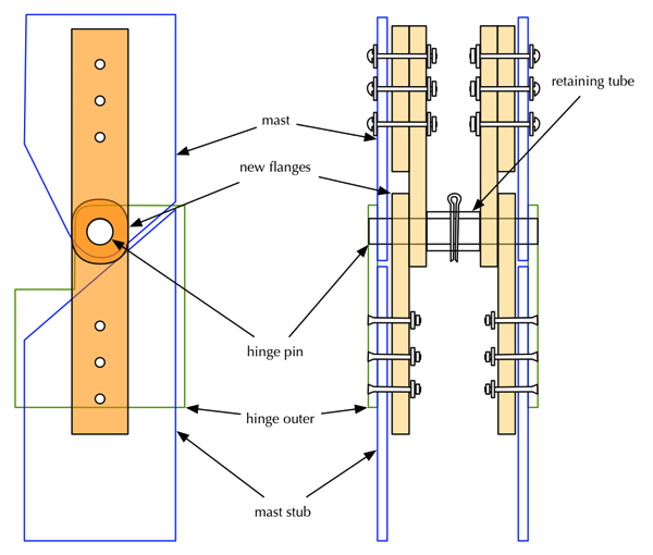
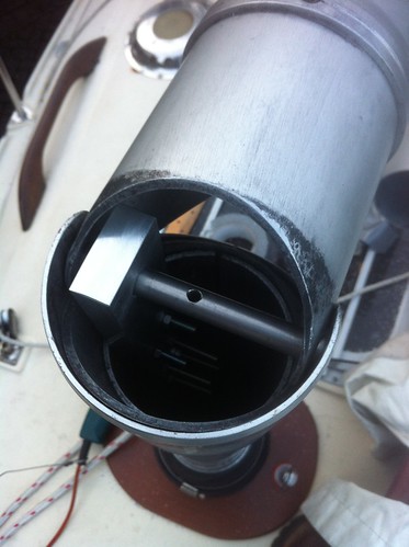
On Sunday I made the two upper flanges and spacers, again using the first flange as a template. By this stage I was getting pretty quick, and drilled the mast with confidence. Because there’s a ring here to support the mast sleeve, there was only room for four screws. Also, with the flanges so close together, it became impossible to put nuts on the back of the screws! At this stage, Dad suggested capturing the nuts within the flanges. I drilled 8.5mm recesses into the flanges and (gently) hammered in nyloc nuts, with Duralac to prevent electrolytic corrosion between the stainless steel and aluminium.

IMG_2705

This made assembling the whole thing much easier: I simply had to screw in the machine screws from outside. I also ended up drilling out all the holes to 5.5mm to allow the flanges to move around a bit more and let the pin through without enlarging the 12mm holes at all.

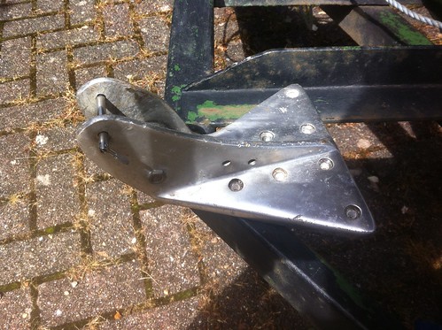
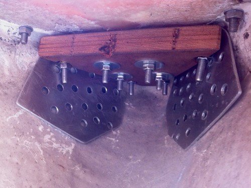
Time for final assembly. I dismantled the whole thing, treated the wooden spacers with three coats of exterior wood preserver, painted Duralac into all the holes, and screwed everything together. Finally, the pin went into place with a few gentle blows from a mallet — just right. Here’s the result.

IMG_2713

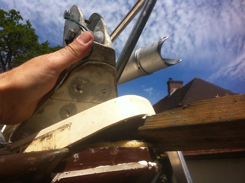
The red stuff is my blood. And with the temperature at over 25°C there was quite a lot of sweat involved too.

IMG_2715

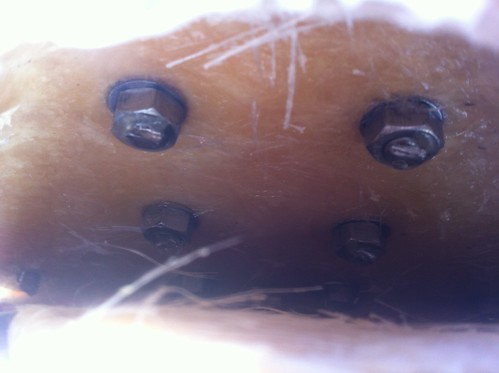
And here you can see the screws in place painted with Duralac. Blood, sweat, and Duralac pretty much sums it up.

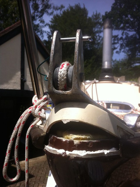
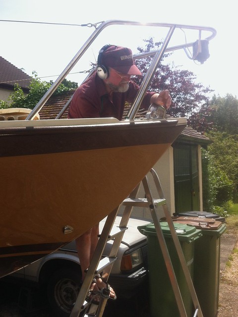
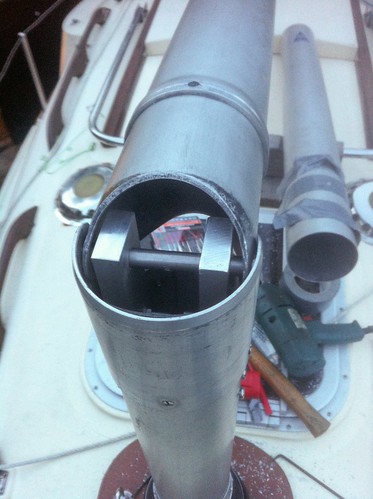
But what fantastic results! We raised the mast, again with guy ropes just in case. It felt rock solid. Once we had it vertical I asked Mum and Dad to be ready on the guys and tried to push the mast from side to side. Nothing. In fact, I was unable to get it to wobble at all in any direction, except backwards in order to fold it away. Here’s a picture of the hinge with the mast raised.

IMG_2717

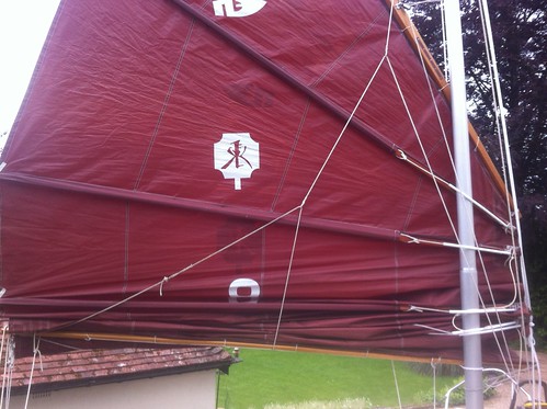
The mast sleeve slid neatly into place over the whole thing, making everything even more rigid. You can see the sleeve covering the hinge in this picture of the rig reefed down to three panels.


IMG_2718

During that afternoon I had to make several changes to fittings at the top of the mast. No problem: down with the sail, up with the sleeve, and just fold the mast down. No need for help. It feel like about 15-20kg of force: no problem at all. And I’m pretty sure it’ll work just as well on a canal or river.

So now Tammy Norie can duck under bridges with ease, opening up a lot of opportunities for inshore exploration.

Many thanks to everyone who suggested solutions, but especially to Dad who gave me advice at every step of the way and taught me to use his tools. Hurrah for engineering!

8 Comments

Filed under mast, Repairs and Modifications

Mast hinge design

I’ve had some useful discussions about Tammy Norie’s dodgy mast hinge with members of both the Junk Rig Association and the Cambridge University Yacht Club and have come up with a winning design.

Many people’s first suggestion was to somehow prevent the pin from popping out by using countersunk screws.  The problem with this is that the mast sleeve is only about 3mm thick and doesn’t have a lot of depth for countersinking.  I’m also reluctant to weaken it any further.  It already seems like not enough material to support a wobbling mast.

Another common suggestion was to make the pin longer and somehow shorten or remove it just before dropping the mast sleeve. Various ideas involving springs, bolts, and slots in the sleeve were suggested. The problem there is that if I’m single-handed on the boat on the water then I won’t be able to let go of the mast, remove or adjust the pin, and drop the sleeve in a safe way.  At some point the mast will be insecure.

The best suggestion came from Igor Gotlibovych of CUYC. (Igor is, with two friends, fixing up their yacht Auriga for an imminent circuit of the South Atlantic.) He sent this picture, saying “you could add two of these, riveted to the inside of the lower section of the mast, to provide extra support.”

Junk

In fact, it’s even simpler than that, because the flanges don’t even have to be bent. Here’s the sketch for reinforcing the lower part.

Hinge reinforcement

In fact, since I’m at it, I’ll probably reinforce the hinge connection to the upper part as well, like this.

Double hinge reinforcement version 2

A good thing about this design is that the exact dimensions of the flanges aren’t critical. The plan is to visit a nearby metal merchant and see what pieces of aluminium alloy he has available. It won’t be hard to cut them to shape. I’ll space them out from the curved inside of the mast using wooden padding, which will also provide a bit of compliance while preventing the flanges from grinding away at the mast.

Watch this space for the results.

4 Comments

Filed under mast, Repairs and Modifications