Monthly Archives: August 2017

Storable colour-matched gelcoat

I accumulate a few scratches and chips in Tammy Norie’s gelcoat each year and would like to be able to prepare small amounts of colour-matched resin. I have RAL numbers for the three colours, but have only been able to find pre-mixed resin with a short shelf-life. Ideally I’d like some sort of storable pigment that I can mix with clear resin in small batches to do repairs over years.

Does such a thing exist? Where from?

I don’t mind if the pigment is not totally consistent in colour after storage. What I don’t want is to have to buy and dispose of large amounts of excess resin.

The curious can see my colour-matching efforts.

IMGA0338

IMGA0336

IMGA0333
(Also posted to the YBW forums.)

Leave a comment

Filed under hull, Repairs and Modifications

The Mantus

After my difficult passage from Sea Palling to Wells I decided to get a bigger anchor. I did not feel safe sleeping on my 6kg Bruce in a very shallow bay in choppy water in the remnants of a hurricane, no matter how tired I was. Well, I got a bigger anchor. A much bigger anchor.

I stumbled upon some quite impressive videos by Mantus Anchors on their YouTube channel. You’ll find plenty of people contesting their results in the comment section, but I could see this was at least a decent anchor. What really attracted me, though, was that it could be packed flat. I did a few measurements and ordered the largest I could fit aboard — their 11kg model. And when their European distributor didn’t have it in stock, Mantus shipped it from Texas at no extra cost!

IMGA0376

The only problem I had were the inconsistent nuts on this anchor. Not only were they Imperial — not surprising given it came from the USA — they weren’t all the same size!

IMGA0386

I replaced them all with 316 stainless M10 bolts, nuts, and spring washers from Sea Screw.

Initially, I kept the Mantus in this triangular locker forward of the mast.

IMGA0381

But then I realized I could pack it into the anchor locker alongside my 6kg Bruce, chain, and rode, so that’s where it lives now.

IMGA0383

Here you can see why this anchor is so great for Tammy Norie. There’s simply no way I could fit an equivalent-sized anchor in her locker. Especially not alongside her normal anchor.

IMGA0387

Using it obviously takes a little planning. You have to put it together with a spanner (one is enough) and transfer the chain and rode from the Bruce using a shackle key.  I have 10m of 8mm chain and about 40m of heavy anchorplait rode, that I joined with this splice. Yarrr!

IMGA0616

I’ve held off on posting about the Mantus because I have not really had a chance to test it in difficult conditions. I did use it when I left Tammy Norie at anchor for a week in Poole Harbour when gales were forecast, but she was also under the watchful eye of Tim McCloy on China Blue.

But after showing it off to Chris Boxer on Emmelène, I thought I might as well tell you all about it.

https://www.flickr.com/photos/41005368@N08/36293738631/in/album-72157684762453053/

3 Comments

Filed under anchor

Twin engine Tammy

It often seems to me that the function of an engine is to stop the boat dead, and do its best to prevent sailing activity. Maybe outboards sulk when installed on a Coromandel because they’re needed so little.

This is the story of what’s happened to the 1983 Honda BF100 that I obtained with Tammy Norie, and how I learned a lot about the insides of engines. You might want to skip it if you don’t want to learn too. Or you can skip to the later parts which involve ropes and the amazing icicle hitch! Believe it or not, this is nowhere near the full story.

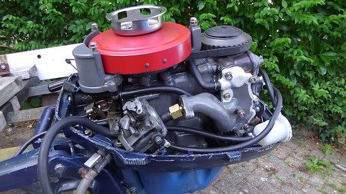
First of all, Tammy Norie was neglected for the winter because of my health. That meant I never winterized her engine properly, and it has been in and out of the water in Fareham Creek twice a day for many months. Of course, when I went to start it, it wouldn’t run. Unlike the BF5, however, the carburettor was not clogged with fuel residue, and we were able to get it running quite quickly by dismantling and re-assembling the carburettor.

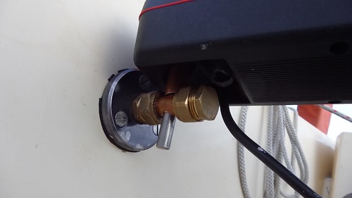
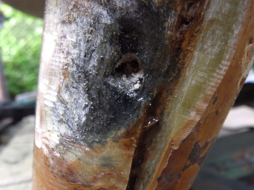
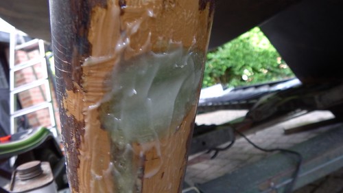
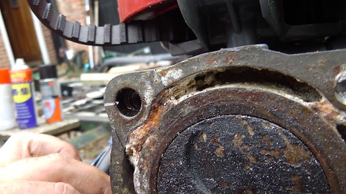
It was then that Dad noticed a bunch of corrosion-like material around the top of the cylinder head.

IMG_20170614_115844

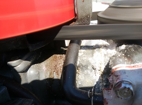
What’s more, we could see water seeping out of this area when the engine was running. The head gasket was leaking, and something nasty was coming out with the water. Uh oh.

This meant removing the head. On a 34-year-old engine that had not been dismantled for at least 30 years. The other sailors at the club were pessimistic.

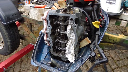
We took the engine home and set it up using the trailer as a stand. Thus began a lot of work.

IMGA0951

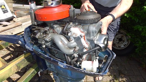
Fortunately, I’d already bought an on-line copy of the engine’s service manual, and that gave quite a bit of information about dismantling it.

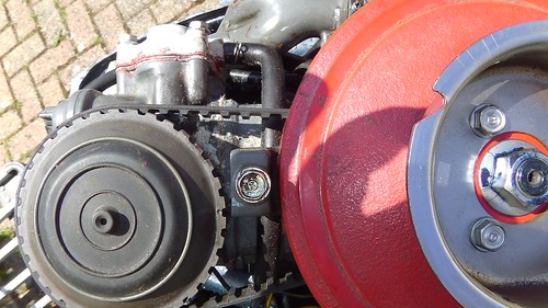
Here’s a record of the positions of the flywheel and timing wheel. The “T” lines up with one side of the middle pillar, while the dot on the wheel lines up with the other.

IMGA0954

Off with the timing wheel.

IMGA0955

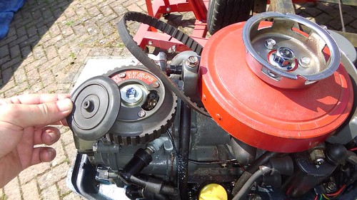
Then I was able to remove the rocker box cover. These bolts came undone reasonably easily, though not completely smoothly. Inside you can see the rockers on the cam shaft, and the tops of the engine valves. Everything is nicely coated in engine oil.

IMGA0956

Then it was time to undo the six head bolts. You can see one of them at the top-right of the rocker box in the picture above. The other five are recessed some way back. This was tricky. Four of the bolts made a nice click and came free. Two of them resisted. I wiggled them. We applied penetrating oil and cold shock. Then I wiggled them a bit more. And a bit more. And then they both sheared off.

Here’s what’s left of the middle-left bolt. The top-right bolt sheared some way down and so was less visible.

IMGA0960

Even with the bolts broken, the engine head showed no sign of coming loose, even after some sharp taps with a mallet.

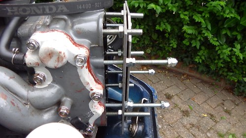
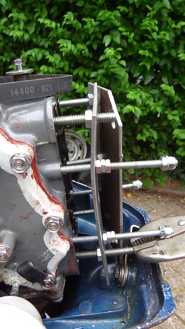
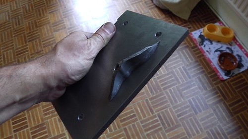
We rigged up some plates using the rocker box bolt holes and some studding to try to press down on the remains of the broken bolts and on the threads of the head bolt holes. By progressively tightening these against each other and tapping the head with a mallet, we hoped it would come loose.

IMGA0976

Well, the plates buckled.

IMGA0978

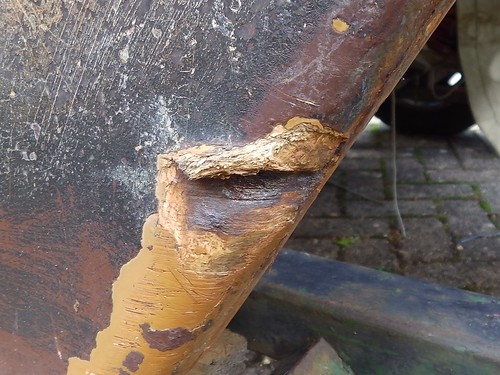
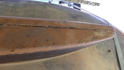
And then finally, the head came loose. I was very pleased for a few seconds until I realized just how it had happened. Can you see?

IMGA0979

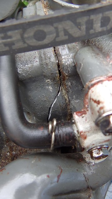
That’s a crack in the engine block. The middle left bolt hadn’t moved. Instead, the block cracked and the bolt took part of it away.

At this point I thought the engine was dead. A cracked block is pretty terminal. But I wasn’t prepared to give up completely, and in any case I wanted to find out what was wrong under that head!

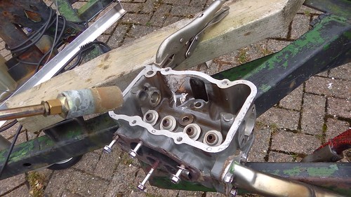
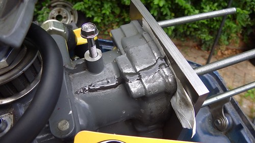
Our next move was to drill out the bolts. We should have done this first, instead of trying to press them out, but we hoped we could avoid damage. Drilling out bolts is tricky and you usually end up with a larger hole than you want. Here’s a picture part-way through drilling out the top-right bolt, with some wooden wedges trying to persuade the head to come loose.

IMGA0980

Finally, the bolt was cleared and the head came away. Now we could see what was going on inside the engine.

IMGA0982

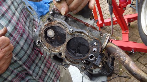
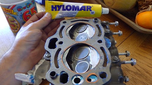
The first thing to note is the clean grey metal at the top edge. That’s the part of the block that cracked and came away with the head. It’s still attached to the middle-left broken head bolt.

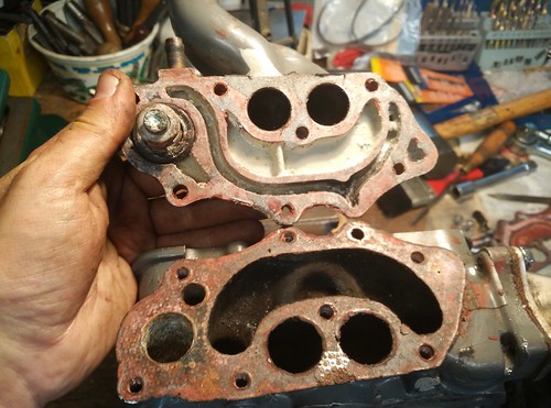
You can also see that the upper cylinder exhaust valve is very different in appearance from the others. It was not coated with carbon. It was also not closing properly, and rotated in its seat. It’s likely the upper cylinder was not firing properly at all. This problem may have been caused by the next thing.

IMGA0983

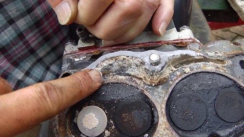
All that off-white junk around the cylinders is some kind of deposit from the water. It’s not meant to be there. Those are meant to be empty channels for cooling water to flow around the cylinders. The top cylinder isn’t getting any cooling. In fact, as I found out much later (after a lot of unclogging) this meant water was not circulating around the cylinders at all. It’s liklely that the only reason I hadn’t damaged the engine by overheating is that I never ran it for more than a few minutes at a time.

The material looked very old. I’m pretty sure it could not have accumulated in the engine while it was upright, since all the water flows down away from that spot. I suspect it is the result of the engine being stored with water in it, and then possibly a build-up over time.

And this is the cause of the water leak around the head. Water was trying to get past this clog, and had forced its way through the old gasket. The “corrosion” on the engine wasn’t from the aluminum (which is fine) but was more of this gunk from the water.

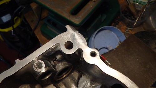
Here’s the corresponding part of the engine block. Again, those channels around the cylinders are supposed to be clear.

IMGA0985

We took the head to the drill press and drilled out the middle-left head bolt, separating the broken piece of the engine block.

IMGA0990

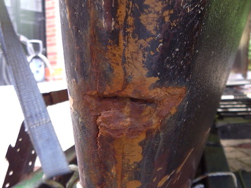
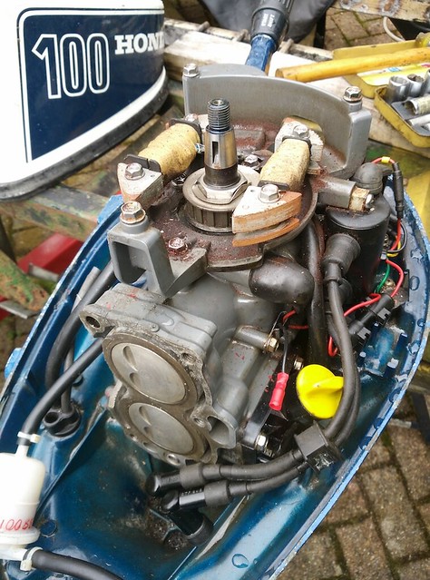
Having cleaned off the block, I noticed a second crack, tucked underneath the flywheel.

IMGA0992

IMGA0993

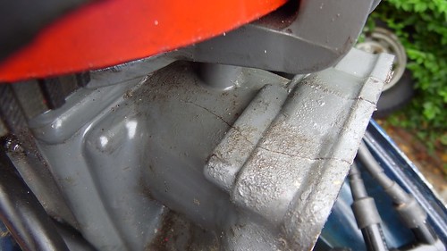
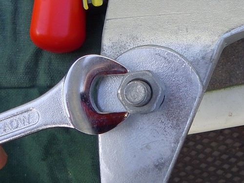
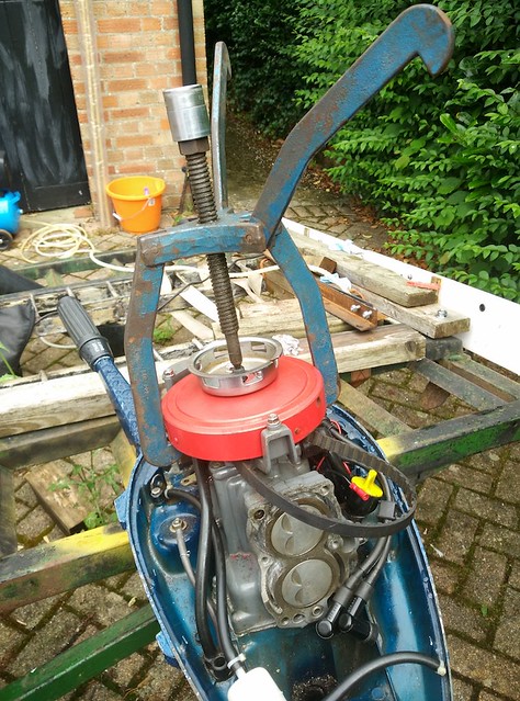
So now that flywheel has to come off. Yet again we are confronted with something that hasn’t moved for 30 years. The flywheel bolt required a huge amount of strength and a very long wrench to loosen, and then of course the flywheel itself refused to come off.  Luckily Dad had a large bolt puller, and with a lot of tightening and persuasion with a mallet, the flywheel came loose.

IMG_20170629_101701

IMG_20170629_102422

At this point I spent a lot of time cleaning the white deposits out of the water channels using a mixture of pointy metal tools and stiff brushes. We did try dissolving the stuff using descaling acid, but it had no effect. Whatever it is, it’s very tenacious.

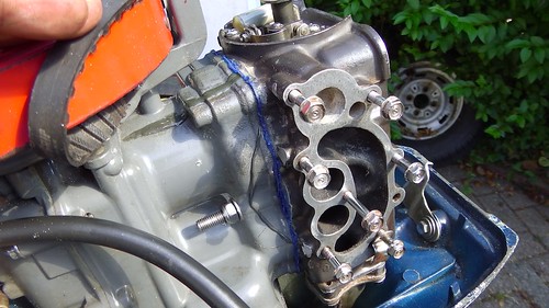
The water channels inside the head are quite convoluted, and it took some time before I understood how they connected up. I even sucked some cotton thread through the various tunnels with a vaccuum cleaner to try to figure it out.  After a while I deduced that there must be a water exit hidden somewhere in the head, and decided to take off the manifold.

IMG_20170629_115400

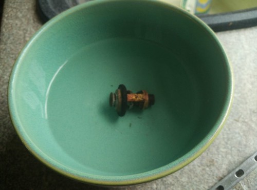
I found more water channels, fortunately clear of debris, and the key to the mystery: the clogged up thermostatic valve.

The way things work is this: the impeller pushes water through the engine. When it reaches the engine it has two ways to go: it can bypass more-or-less straight into the exhaust, or it can flow around the cylinders, past the thermostat, and into the exhaust. But when the engine is cold, the thermostat is closed. As the engine heats up (to about 80C) the thermostat opens and allows cooling water to flow around the cylinders. In this way the engine temperature is regulated.

Unless the thermostat is clogged.

I cleaned and tested the thermostat with hot water from the kettle. It was fine.

IMG_20170703_091405

Then we tested the water flow through the engine by squirting it into the inlet using the garden hose.

IMG_20170703_095257

All good. Now, what about those cracks?

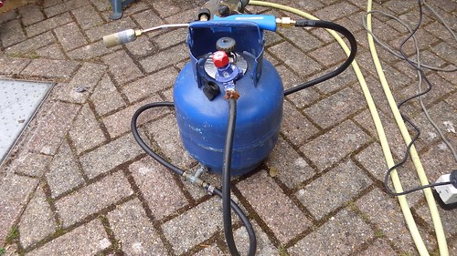
After a bit of searching, I found out about aluminium brazing, and even found a brazing rod supplier near a friend’s house. I also bought a butane torch and attached it to my boat’s butane supply.

IMGA0032

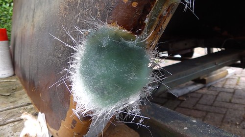
As a trial, I had a go at brazing a small piece of the head that I’d broken off with the mallet while trying to get it off. Here you can see it held by the mole grips.

IMGA0039

This took a long time. I think it took over 45 minutes to get the head hot enough to melt the rod. I suspect my torch isn’t very good, but also the aluminium head was conducting the heat away quite efficiently. I needed to get the metal up to about 300C, and that proved very difficult.  It worked eventually.  Here’s a picture of the repair after some clean-up.

IMGA0043

At this point I realized that I probably wasn’t going to be able to braze the cracks in the block. I wouldn’t be able to get the repair areas hot enough with  my torch. Even if I could, the heat would be damaging other parts of the engine. I’d have to completely disassemble everything before I started.  The amount of effort was starting to go from merely excessive to ridiculous.

In the meantime, another problem had emerged. I took the gearbox off the engine to gain access to the water inlet, and also to check the impeller. But I couldn’t get to the impeller, because the engine shaft was stuck fast on to the gearbox pinion shaft. There’s a simple square joint between them, but it wouldn’t budge.

I tried oil and hammers. I tried fire and ice.

IMGA0045

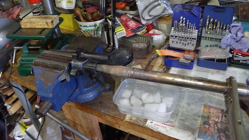
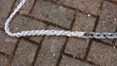
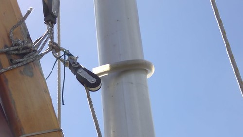
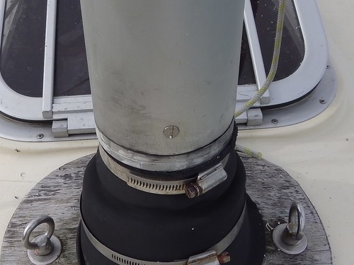
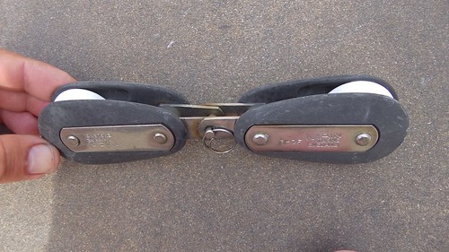
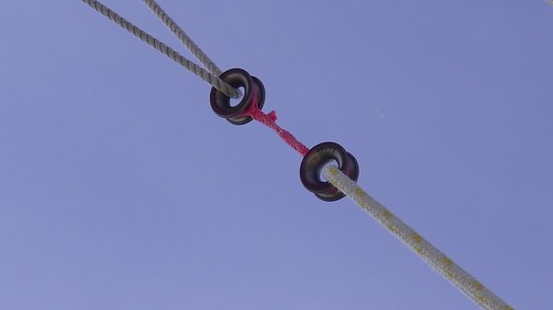
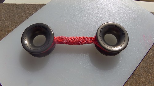
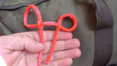
Next, I tied icicle hitches around the shafts and applied a lot of force using a 2 tonnes hydraulic crane.

IMGA0051

IMGA0053

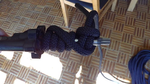
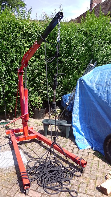
Nope. The main thing I learned from this is that icicle hitches are awesome. One of those hitches is tied to a highly polished smooth stainless-steel shaft!

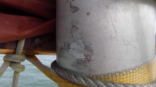
Eventually I moved to applying force using just the 8 tonne hydraulic ram. The icicle hitch on the smooth end couldn’t quite cope with this, so a shackle was used around a narrowing in the shaft.

IMGA0085

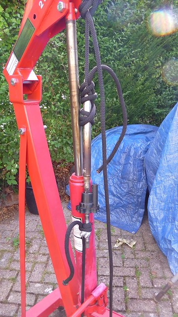
I’m not sure how much force I applied, but the 8 tonne ram was working hard. Still nothing.

The good thing about this is that it tested the black rope. This is rope that I bought to build my Jordan Series Drogue. I’m now very confident it’ll cope with Tammy Norie’s expected maximum 1 tonne load.

There were also some other attempts involving hanging the shaft from a chain, applying tension, and heating it. I suspect the only way to get enough concentrated heat would be using an induction coil.

Unforuntately, with this shaft fused together it’s impossible to change the impeller. An impeller failure at sea means an overheating engine. And so the engine was looking less and less viable.

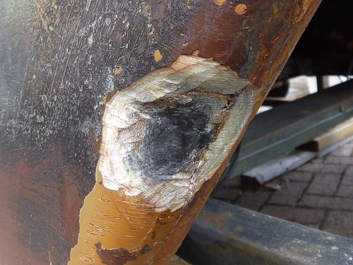
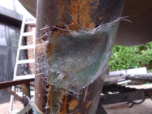
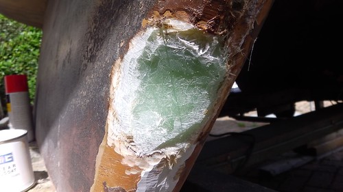
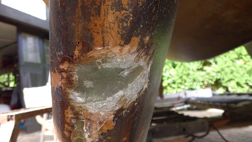
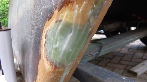
Back to the cracked block. I decided I’d see if it could be repaired using an epoxy compound. Remember, the cracked aluminium parts are in the water jacket, not in the combustion cylinders, so they’re not under explosive engine pressure, so it’s plausible that an epoxy might work. After a bit of research I decided to try Plastic Padding Super Steel Epoxy Weld.

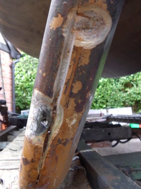
I bought flat steel section to ensure that my work ended up flat, and bolted the broken-off piece of engine block to it.

IMGA0046

I attached this assembly to the engine, using the epoxy weld to seal the crack and re-attach the broken-off piece. The masking tape was to prevent the plate becoming bonded to the engine block.

IMGA0067

I re-assembled the head, re-seated the valves, and made everything clean and beautiful. Then I put in a new gasket and bolted the engine back together.

IMGA0077

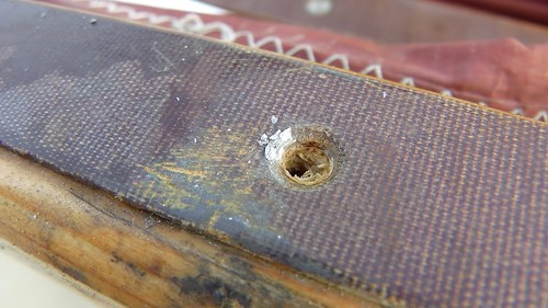
In this picture you can see a modification to the middle-left head bolt. I drilled right through the block and added a nut at the back. This is because I did not feel I could rely on the epoxy weld under tension. The new arrangement compresses the broken-off piece to the block instead.

IMGA0078

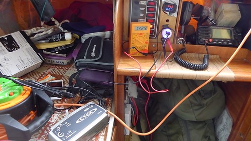
And finally, I tested it using butane as fuel.

IMGA0081

It started easily, and ran beautifully.
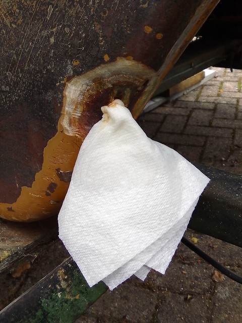
And leaked water.

Unfortunately, the epoxy failed to seal the water channels. Although my work had cleared the water blockages, fixed the exhaust valve, improved compression, and made everything smooth, we still had a leaky engine with an unmaintainable impeller.

At this point I decided I’d had enough. Up to this point I was learning a lot about engines. I’d never dismantled and reassembled a cylinder head before, and it was all worth doing just for that. But now I was faced with doing it all again, with uncertain results.

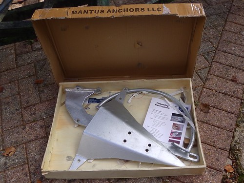
Fortunately, on that day, another Honda BF100 appeared on eBay. The same engine. The one I’d just learned inside-out. What’s more, I had nearly a whole engine’s-worth of spares. It was ideal. So I bid, won, rented a car, and drove 450 miles to collect it.

IMG_20170716_163436

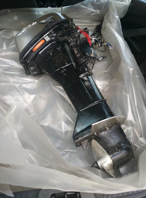
That’s the engine that’s now in Tammy Norie.

As you can imagine, I was able to give it a very thorough service. And I made sure the head bolts turn!


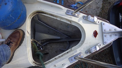
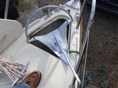
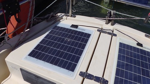
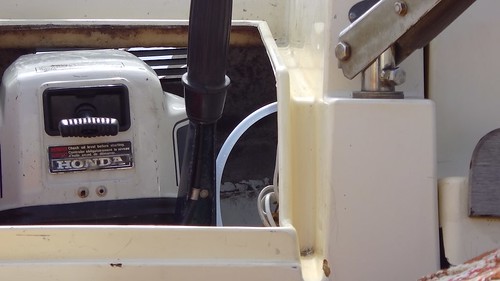
Postscript: I think my problems with engines come partly from a design problem with the Coromandel. Having an outboard in a well is quite neat, but there’s no easy way to lift the engine out of the water when it’s not in use. A look around will quickly show you that everyone lifts their outboards. The gearbox and lower parts of the engine aren’t meant to spend their lives immersed in salt water. My problems with the shaft are the result. I have yet to come up with a neat solution.

3 Comments

Filed under engine, Repairs and Modifications

Tammy meets Mr Fox

I met Chris Edwards and his self-converted Red Fox Vision at Newtown Creek on the Isle of Wight, and we sailed in tandem up to Southampton Water.

There are also photos on Flickr, but this is my favourite.

IMGA0292

Apparently there are only five Red Fox Vision yachts in existence, and Chris is very lucky to have this one. It’s one of those smart and innovative designs that didn’t appeal to the conservative yachtsman. Just the sort of thing for a radical junk rigger!

17 Comments

2017-08-23 · 17:37

Aerojunk Coromandel

In 2015, Gavin Dalglish put me in touch with Paul McKay, who had sent him designs for an aerojunk rig for the Coromandel. I’ve just managed to get back in touch with Paul, who’s given me permission to reproduce his drawings and documentation here. I thought it was timely given the discussion of Emmelène’s split rig, and the sudden burgeoning of aerojunk rigs by Pete Hill and others in the JRA Magazine issue 74. I’d much rather have this somewhere public and useful than sitting in my inbox!

Here is one of Paul’s drawings, over the top of the standard rigging of the Coromandel.

There’s more complete information in Paul’s document, AeroJunk Folio Interim 2.  In addition, Paul wrote to Gavin:

I have drawn a suggested AeroJunk sail plan for your boat. I have overdrawn it on an original line drawing from Newbridge for comparison. You can see it is semi-elliptical. The original ‘lead’ appears to be 7.5%. This design will give a ‘lead’ of 10.25%. If there is a problem with weather-helm or too small a rudder then this will help a lot. Hasler/McLeod allow for a lead up to 12%.

The position of the original C/E and the position of your mast determines that this AeroJunk design becomes ‘low-aspect’. (My mast is further aft and forces a high-aspect design) The new C/E will be lower than Newbridge’s, so although this sail is 199 ft2 or 18.4m2, you should be able to carry the extra sail without penalty. Because of the camber in both sails it should go like a train!

I have drawn a batten angle of 1.5% above the horizontal. This works nicely on my boat. The batten spacing is 3ft or 915mm. The batten width will be such that the main produces a 1:8 camber. I haven’t worked this out yet but the boom will be somewhere between 600 and 900mm wide at the mast. You will need a spreader yoke about 400mm wide hung just below the front mast top. The lazy-jacks will be fitted to eyelets at 350mm centres on this yoke. Although the jib looks narrow it is slightly larger than mine so will work well.

Because of the low-aspect, there will be no problems with jib/main balance. Finally I have drawn a deliberate roach at the top of the mainsail. I suggest you incorporate that by fitting short permanent battens to support the roach. If you do away with the roach you will increase the ‘lead’ slightly. Something you can try if you still have weather-helm problems.

Gavin was planning to build this rig, but I have not yet managed to get in touch with him to find out how it went.  The last I heard, Gavin was drying out his Coromandel for osmosis treatment somewhere near Vannes in Brittany.

Here is a picture of Paul’s Etap 23i with a similar rig. Note the different sheet arrangement.

SH100508

Paul wrote to Gavin:

Having finished my batten remodelling I took the boat out for a sail on Tuesday. It was a perfect Force 3 wind and I got a broad reach from just outside the marina for two miles before I had to tack. I was getting between 5 and 5.5knots. The tack took me close hauled and I still got 5.5kn although I was well heeled over by this time. That close to the wind I have the rudder hauled towards me as the weather-helm naturally increases. But this demonstrates how efficient the AeroJunk can be. My waterline length is 19 feet compared to your 16 feet so my maximum hull speed is 5.66 knots but I have had the boat at 7.5kn downwind. This is with 208ft2 sail. (Well down on the supplied sail area although the official sail area is 196ft2)

In a later message to me, Paul wrote:

Because the top weight of this rig is lighter than a conventional junk I use a downhaul line fastened to the main halyard/sail cringle. I need this to get the last 2 panels down so a combination of pulling the mainsheet and the downhaul does the job.

As Gavin says the forward mounted cockpit sheet jammer and the sheet fastening to the tail of the halyard presses the battens in against the mast and helps to reduce twist in the sail. Because of the twist in the sail, in an Ocean-going boat, I would use heavier canvass and a flatter camber in the top panel that would double as a storm sail. My rig, now 204ft2 (18.95m2) is made from 5oz Dacron.

To keep the sail tidy and effective when reefed I use individual downhauls on battens 1 and 2 plus a combination downhaul fastened to the front of the boom, batten 1 and 2. These have been good enough for up to a Force 5 wind. The strongest wind I have sailed in was a F5 (forecast 19mph) You could have a downhaul for every batten if you had enough deck sail clutches.

I suffered a blue-sky knockdown last year when hit by a gust on a sunny day. I think I got to about 50 degrees heel. The gust spun the boat round in its length while I hung grimly on to the safety rail. The whole thing lasted about 20 seconds. I estimated later it to be a Force 7 with all sail standing. The only effect was to stretch 4 of the 50lb locking cable ties.

Today, Paul wrote to me:

I am just about to start [a folio on the Aerojunk] again. I have also just designed a new sail for Miranda, slightly larger at 20m2 and have made new battens from telescoping aluminium tubes. The sail is being made now and I expect to get it in a couple of weeks.

It was interesting to discover that Pete Hill had made AeroJunk sails for his new boat, Oryx. I believe he has now designed and made AeroJunk sails for 2 other boats in New Zealand. He has done this without any reference to me so must have got all his information from my original articles in the JRA Newsletters. […]

When I finish the folio I will hopefully publish it in the JRA.

So we can look forward to some very interesting updates from Paul. In the meantime, this article will I hope encourage and interest you all.

4 Comments

Filed under Uncategorized

Little jobs roundup, 2017-08

I usually make posts about big things I’ve done, and not many about the hundreds of little jobs I do on Tammy Norie. I thought I’d start a series of occasional posts noting these, and if anyone wants more details they can ask in the comments.

The 30-year-old mushroom vent over the heads compartment cracked. The plastic looked like old ceramic. Replaced, although I don’t much like the quality of the new one. I’ll keep a look out for a stronger replacement.

IMG_20170618_081802

IMGA0169

I bought a CTek battery charger before going to the Netherlands in 2015. When I got there, it didn’t work! What’s more, when I tried to return it to the shop, they’d closed down, and their parent company had gone bankrupt. CTek eventually agreed to send me a new one directly, but it has been in its box for two years, untested. In a rare stay at a marina, I decided to test and install it.

IMGA0132

Here it is installed below the main electrical panel in what would be the engine compartment on a bigger boat. Below it you can see the gas alarm (below head level when sleeping) and a big circuit breaker. The solar panel regulator promises to prevent overloads, and the every switch on the panel has a circuit breaker too, so I’m pretty well protected from shorts. I have a better main breaker for the panel when I re-make it.

IMGA0137

At the back of the compartment you can see water-tight plastic boxes with spares and parts inside. I label them using tape and a big marker pen, so that I can pull out the right box from deep in the compartment.

I shortened the plastic tube I put around my yard parrel to prevent chafe. I can now peak up a few more degrees.

IMGA0160

I finally stuck down my second solar panel. It’s been attached with duct tape for the past year. In spite of that, it’s never tried to escape overboard. I only really need a second panel because I installed a fancy main radio with GPS and AIS alarms, so I that I could sleep more soundly on offshore passages. I don’t use this radio much inshore.

IMGA0163

I fixed yet another leak. This one was through the bolts fixing the pushpit rail foot. This was a good test for butyl tape, which I’m favouring over Sikaflex these days. It’s as easy to handle as Blu-tack and seems very effective.

IMGA0255

Tammy Norie’s bilge is too small to fit a proper electric bilge pump. I bought a very cheap submersible Chinese pump from eBay, connected it to some narrow hose, and ran that alongside the main hose, then through an existing hole and into the engine well.

IMGA0257

IMGA0258

This pump is not going to save any lives. It takes a few minutes to empty even Tammy’s tiny bilge, but it’s nice to be able to press a button. And the installation interferes with nothing else.

My old tiller pilot got wet inside, corroded, and stopped working. I sold the remains at a boat jumble. My uncle then gave me an old one he had in the attic. The same model. Great, except that it didn’t come with the mounting bar. Dad suggested the thread on the mounting socket might be a pipe thread. He was right! It’s a 20mm thread as used on 15mm copper pipe fittings. A quick visit to a hardware shop and I have a new mount.

IMGA0317

The mast hinge sleeve has a habit of walking around the mast until it jams up. At one stage, I had to use a mallet to free it up so that I could lower the mast. So I’ve drilled and tapped a screw hole to keep it in place.

IMGA0168

This revealed a probem further up the sleeve. There were some quite deep gouges in the aluminium near the boom.

IMGA0170

The culprit? Countersunk screw heads sticking up from the strip of material on the boom designed to prevent chafing the mast! Fail.

IMGA0218

I’ve tightened up these screws on all the strips, and increased the depth of the recess in some cases. It might be better to use some other kind of fixing. If you look carefully at this picture you can see that the screws at the end have been pulled inwards, as if the mast strip has shrunk, or the boom has grown.

IMGA0220

The rivets holding the handle to my Captain Currey rigging knife came apart, and the handle fell off. So I replaced them with nice machine screws in new recesses, oiled the handle, and sharpened the blade on my stone too.

IMGA0164

Lastly, I’ve been gradually working my way around the woodwork, rubbing off the old brown paint and some of the UV damage, then treating the wood with oil. You can see the contrast here. Imagine when it’s all done!

IMG_20170820_111025

I’ve done the same to the tiller, but unfortunately I discovered that under the paint the tiller is not a very beautiful piece of wood. So that will be getting some new paint, and perhaps I’ll get hold of a bit of hardwood and whittle a new tiller on passage.

That’s all for now. I hope you enjoyed seeing the small ways in which Tammy is improving.

1 Comment

Filed under Repairs and Modifications

A nasty hack on the shin

In the summer of 2015, while departing for the Netherlands, I hit the concrete footing outside Fort Blockhouse in the entrance to Portsmouth Harbour. There’s no excuse for it — I was cutting a corner inside the channel marker, confusing it with the next one out.

This Google Maps image shows the footing quite clearly, but not the channel marker. In reality, this concrete is hidden under water, but you can see how nasty it is.

Here’s a photo I took much later at a very low tide.

IMGA0648

It was a big knock for Tammy, but I didn’t get to see the damage until I hauled her out in early 2016.

IMGA0574

Oh dear. That’s the forward edge of the starbard keel, about half-way down.

IMGA0575

And that’s a bit further up on the inside.

I ground away the damaged fibreglass. The hole went right through the skin, revealing a black wet fibrous substance behind. I’m still not exactly sure what it is, but I suspect it is some kind of resin encapsulating the keel ballast.

IMGA0588

The material stayed wet, so I decided to investigate by digging a small hole into it.

IMGA0589

The hole wept a black fluid, which kept flowing for two days, gradually slowing down. Once it stopped flowing, I stuffed tissue paper into the hole to encourage the moisture to wick out of the material, and eventually it dried up.

IMGA0595

What was left was slightly fibrous and crystalline.

IMGA0591

I decided not to worry about it any further at the moment. The next time Tammy is ashore for the winter, I may drill holes into the bottoms of the keels to drain them and then re-seal them in the spring, possibly with some kind of shoes attached. The undersides of the keels are looking worn, as you can see in this picture taken while she was on a crane later that year.

IMGA0626

Here are both the holes, cleaned up and dry. Some of the fibreglass along the forward seam was looking a bit dodgy, so I decide to patch that as well while I was working. You can see where I’ve cut a groove between the holes.

IMGA0590

With that done, I started to lay up glass to repair the hull. As I’ve seen recommended in several videos, I laid down a large patch first, then added smaller patches until I’d built up a repair.

IMGA0596

IMGA0597

I then ground away the excess to restore the keel shape.

IMGA0598

IMGA0599

With hindsight I could’ve added another layer of glass.

Finally, I applied clear gelcoat, then sanded the result smooth. I somehow forgot to take a picture of the smooth result!

IMGA0600

IMGA0601

You might wonder why I chose to use clear gelcoat. Well, these repairs are below the waterline, and will be covered by antifouling, and I didn’t see any cosmetic reason to hide them. I’d rather be able to see clearly where my repairs are and perhaps see into the top layers of layup for problems. I also have no motivation to hide my mistakes and repairs, as you can tell by this blog!

This year I dried out Tammy at Portchester Sailing Club, to inspect and clean her bottom, and that gave me a chance to look at my repairs.

IMGA0943

IMGA0944

There’s no sign of any problems, and I’m happy that Tammy is seaworthy. I plan to make a more thorough investigation of both keels when she comes out this winter. In particular, I think I’ll make some small inspection holes from inside the boat and send in my dad’s endoscope to see what’s there. I’ve read articles from Corribee owners saying there are quite large voids above the ballast, and even one suggesting they might be a good place for water tanks.

If you have any suggestions for improvement, or ideas about what’s inside my keels, I would be very interested to hear.

5 Comments

Filed under hull, Repairs and Modifications

To Purbeck with Emmelène

I’m planning to sail from the Solent to Purbeck and Poole next weekend in company with Chris Boxer aboard Tammy’s sister Emmelène. This should be a fun outing. I’ll be meeting family there, but more interesting for my readers, this will be a good chance to compare my flat Hasler-McLeod rig with Emmelène’s split rig under a variety of conditions.

Here’s the plan:

  • Thursday around 13:00: Tammy and Emmelène rendezvous in the eastern Solent and ride the current to the west. Most likely overnight at Yarmouth, Lymington, or Keyhaven.
  • Friday 13:00: Pass through west Solent tide race at slack water and ride the current to Studland Bay.
  • Monday 04:00: Catch the tide change to sail back to the west Solent channel before it becomes impassable at around 11:00.

As always, if anyone wants to meet up please get on touch. (My nephew and niece get priority as crew on Tammy Norie, but have not yet confirmed.)

6 Comments

Filed under Plans

Sister Rings

When I first rigged up the Hebridean wind vane self-steering, I used some hard anodized aluminium rings instead of blocks to run the tiller control lines. These rings are mechanically simple and very slippery, and they’ve done a great job. A couple of years ago I started to think about where else I could apply them.

Tammy Norie has “sister blocks” in the main sheet to evenly distribute load across battens. These are simply two blocks attached back-to-back.

IMGA0306

There’s nothing wrong with this, and Tammy’s are in good condition, but I wondered if something simpler and lighter could be made from anodized rings. And here it is: the “sister rings”!

IMGA0313

IMGA0904

This is such a simple idea that I can’t believe someone hasn’t done it before. It’s just two rings joined together with a double eye splice. In this case, two 16mm Barton “high load eyes” joined with Dyneema.

This is a simple, lightweight, cheap, strong, and easy-to-make alternative to sister blocks, with comparable friction, unlike the traditional wooden euphroe.

To form the splice using single-braided line (such as Dyneema), form two eyes like this. Note that the long end passes through the short end (the opposite to what you might expect) and this involves passing one of the eyes through the braid.

IMGA0903

Once you have the rings in place and have tightened the eyes, trim and tuck the ends inside the braid between the rings, fixing the eyes.

I use Selma fids for this kind of splicing.

I’m experimenting with using these rings to replace blocks in other parts of the rigging. It’s easy to carry rings and line and make up or repair things that you need on board, and that very much fits with my philosophy for Tammy Norie!

3 Comments

Filed under Repairs and Modifications, sheet

Emmelène meets Tammy Norie

Chris Boxer has written about our recent meeting at Bembridge on the Isle of Wight. You can find his post on Emmelène’s blog.

IMGA0178

Emmelène has a split junk rig, which means about a third of the sail area is ahead of the mast and formed of conic sections called “jiblets”. These direct airflow over the main part of the panels abaft the mast. The slot effect helps the air stick to the back of the mains and so increases the stall angle, and thus how high you can point. To make this work the luffs of the main sections need to be tight near the mast, like the luff of a Bermudan main.

It’s quite like sailing a stack of small pivoting Bermudan rigs!

IMGA0188

It’s often said that the Coromandel’s mast is too far back. Tammy certainly suffers from weather helm, especially on a reach. But Emmelène has none at all. It’s quite spooky.

If anything she could do with moving the centre if effort aft a touch. The sheets are perhaps a little too relaxed and sometimes it was hard to persuade the sail to swing out.

This is no fault of Chris’s. He bought the rig second-hand to replace the poor “hi-power” rig that came with Emmelène. In fact it was the exact rig the Practical Boat Owner featured in their comparison of junk and Bermudan rigs (using identical Splinter 22s I think) a while ago.

IMGA0216

I look forward to meeting Chris again and perhaps trying it all out in more varied conditions.

IMGA0211

A full set of photos is on Flickr. And a set of photos taken by Chris.

17 Comments

Filed under Logs